A site for audio innovators where hardware design meets DSP, Arduino code, Android apps, PC software and woodworking
-
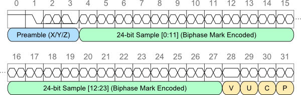
S/PDIF Messaging
Active speakers are a great way to minimize the footprint for home stereo systems, as each speaker has all of the electronics and amplification built into the cabinet, and there is no need for a separate rack of equipment. But this approach has some challenging control issues. Controlling just one active speaker is straightforward, as…
-
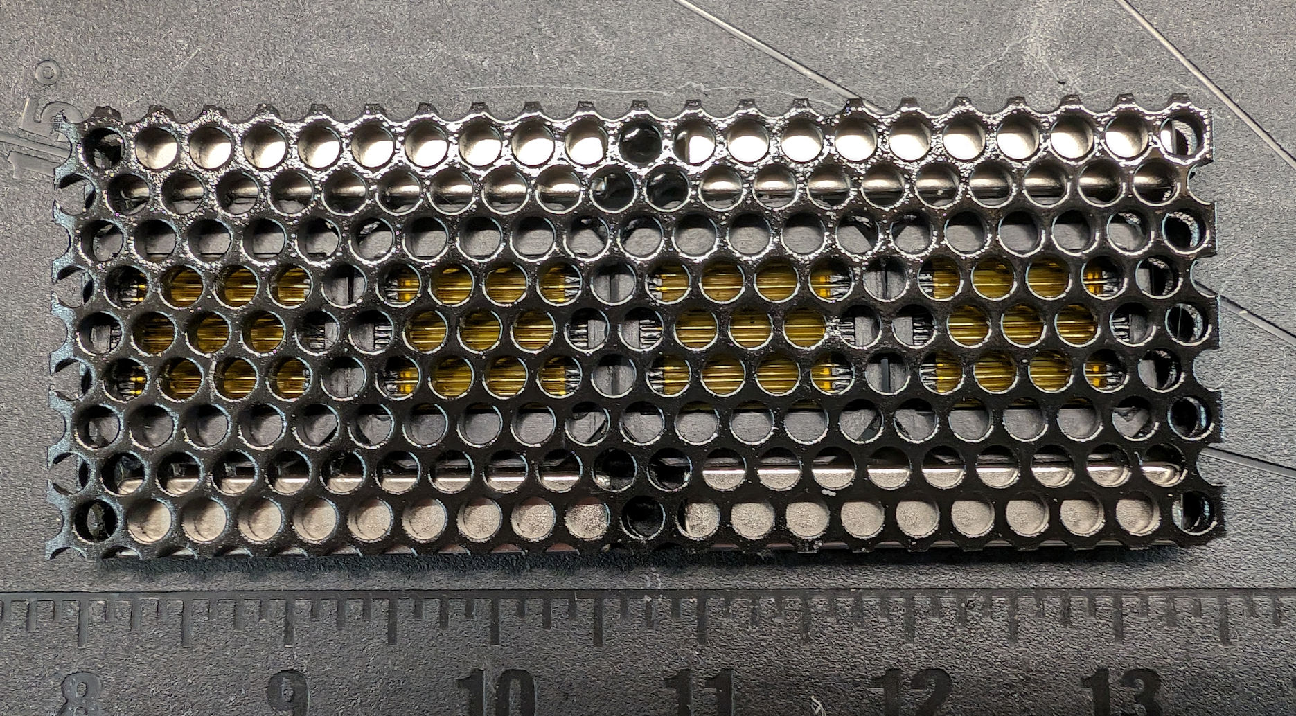
AMT for a Line Array
I needed 48 tweeters to make a 65″ line array, so I came up with a very simple design that I can make quickly. This design uses readily available materials, and it is not overly difficult to construct. I used the small (1″ square) air motion transformer (AMT) diaphragms available at Aliexpress, which are sold…
-
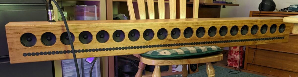
96 Tears
Yep, you are going to cry, cry, cry, cry 96 tears because of all the tweeters used in this project. But, somehow, I got through it, in spite of all the crying, and yes, it was worth it. The picture below is the test setup without the back on for one side. This is a…
-
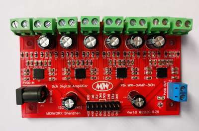
Another prototype (Line Array Amp)
…and an update to the stereo 3-way design I still have some reservations about building the second-generation line array amp described in a previous post, as it requires soldering at least 10 of those 40-pad LFCSP amplifier chips. Those packages are notoriously difficult to solder by hand, and it is way too easy to create…
-
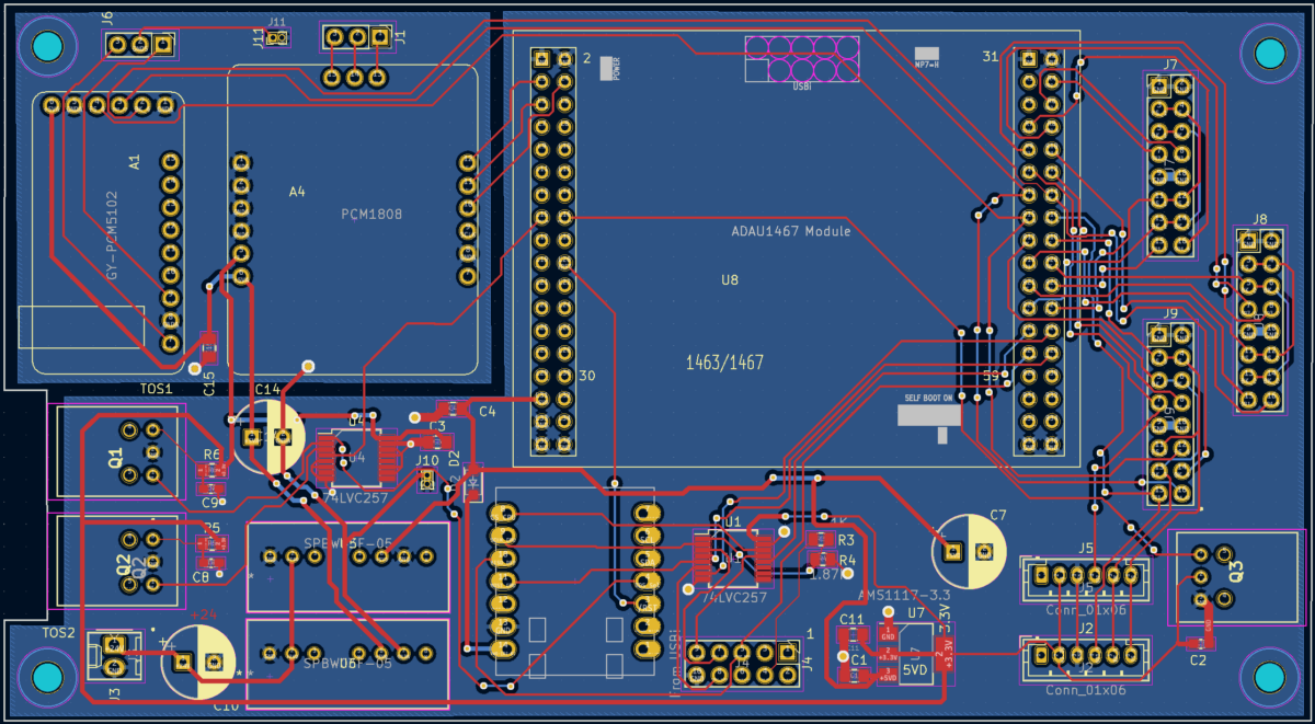
Diversions can be nice
That “diversion board” discussed in the 12/15/2023 post turned out nice. The “motherboard” has two 16-pin SMD chips and a couple of SMD passive components, but it was fairly easy to build. I used socket pins for all the modules, and once you get the hang of mounting them straight on the board, assembly goes…
-
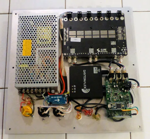
12/15/2023: Another Diversion
The second-generation line array is still in the pipeline, but so is cleaning up some old projects. One that I really liked but needed an upgrade is the “Act 2” active subwoofer with a stereo 3-way plate amp, described in this article. It has two 5-1/4″ subwoofer drivers, with Speakon connectors for the midrange and…
-
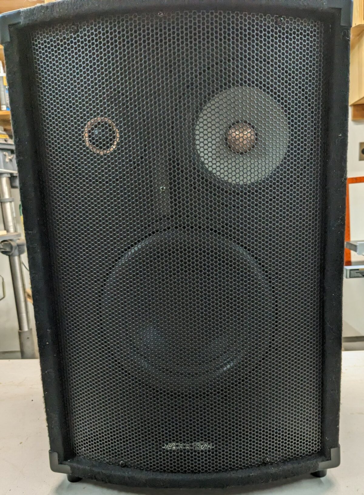
The Russell
Hmmm…what drivers lurk behind that cheap metal grill? And why is the name singular? One of my goals in these retirement years is to use up or dispose of or somehow repurpose a large stash of boards or electronic equipment that I have accumulated during many years of this speaker-building hobby. I’ve got a lot…
-
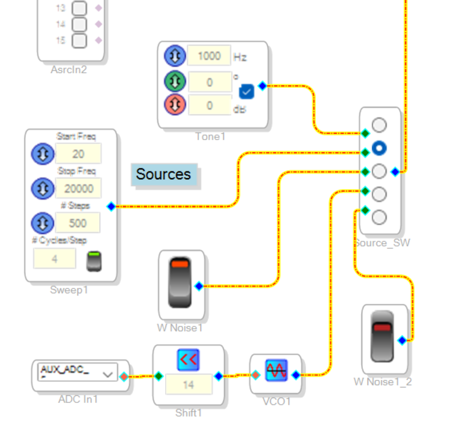
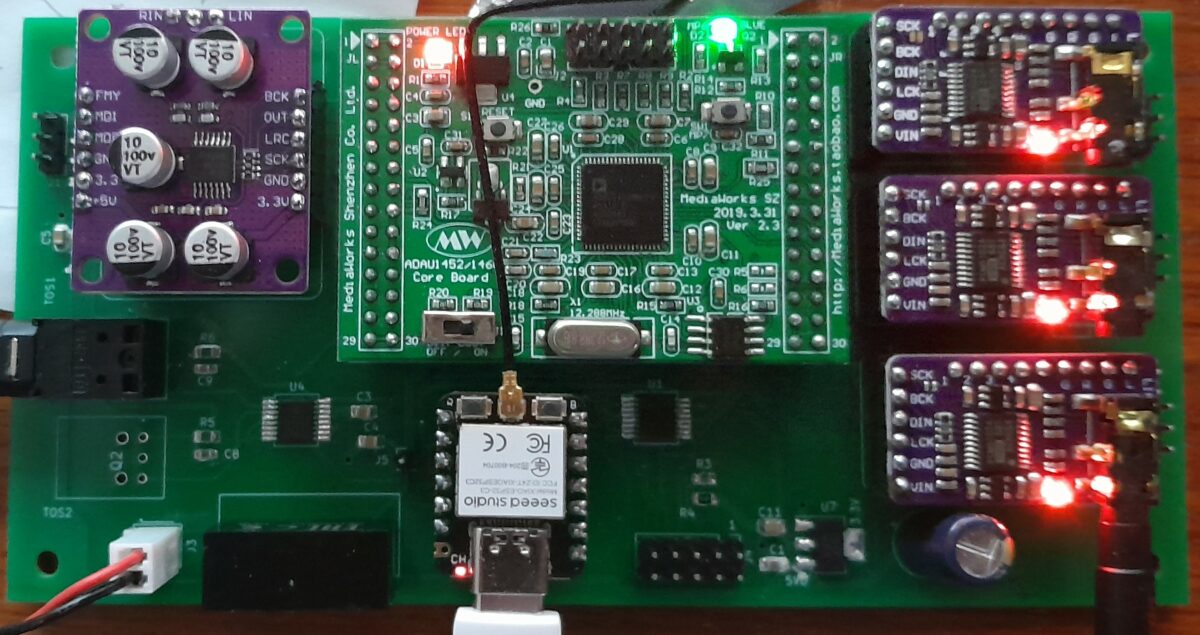
Active speakers with built-in test signals
Sometimes it’s nice to have a tone or sweep generator or even some white noise to test your speakers. SigmaStudio has a good selection of “sources,” even for the ADAU1701, that don’t require a lot of instructions. I’ve never used them before, but I’m finding them very useful for this next round of active speakers…
-
August 2, 2023: Another brainfart
I think that most speaker builders start thinking about their next projects well before the current one is finished. Sometimes that feels like an attention-deficit problem, but the truth is that it is just a healthy part of the creative process. While plodding along with the ADAU1466 code for the Marthas, it struck me that…
-
July 1, 2023: It’s a Slow Train
The “Return of the Marthas” is starting to take shape, but it is taking a long time to tailor the existing software. The Marthas take the 3-way Arduino/Android code and make it 5-way, while upgrading from the AUDA1701 to the ADAU1466. Those changes haven’t been a huge technical hurdle, but there are so many tedious…