…and an update to the stereo 3-way design
I still have some reservations about building the second-generation line array amp described in a previous post, as it requires soldering at least 10 of those 40-pad LFCSP amplifier chips. Those packages are notoriously difficult to solder by hand, and it is way too easy to create bridges to the package thermal tab using the tools that I have. If I were getting younger instead of older, I might take the plunge, but unfortunately, I just keep getting older and less skilled at working under a microscope.
I had previously posted about the 8-channel SSM3582 amplifier board from Midiworx (see below) and pointed out that the board doesn’t support TDM I2S audio, so it wasn’t a viable option for using with the ADAU1452/ADAU1466. Also, the I2C lines aren’t brought out to a connector, so there was no way to program the amplifier chips to support TDM audio. The ADAU1452/ADAU1466 has 48 channels but only 4 output ports, so unless you use TDM, those extra channels can’t be used.

Fortunately, Analog Devices came up with a nice solution for adding extra output ports with the ADAU1463/ADAU1467 chip. This device has extra pins that can be programmed to output extra serial data streams, so that it is possible to have 12 I2S outputs, each stereo, for a total of 24 channels. 24 channels is enough to make a line array amplifier with electronic curvature, using independent delay on each channel. Midiworx is now selling a ADAU1467 module with all those extra I2S data lines brought out to the connectors. So, with the ADAU1467 module and three of the SSM3582 boards, we can make a nice 24-channel line array amp without going blind.
I’ll probably still try my own SSM3582 amplifier boards, since these Midiworx amps are a bit pricey at $70 (it takes 6 of them for stereo!) and because there is no guarantee that they will be around forever. However, I should be able to get started on building a next-generation line array with these boards and debug a lot of software and work on the cabinets.

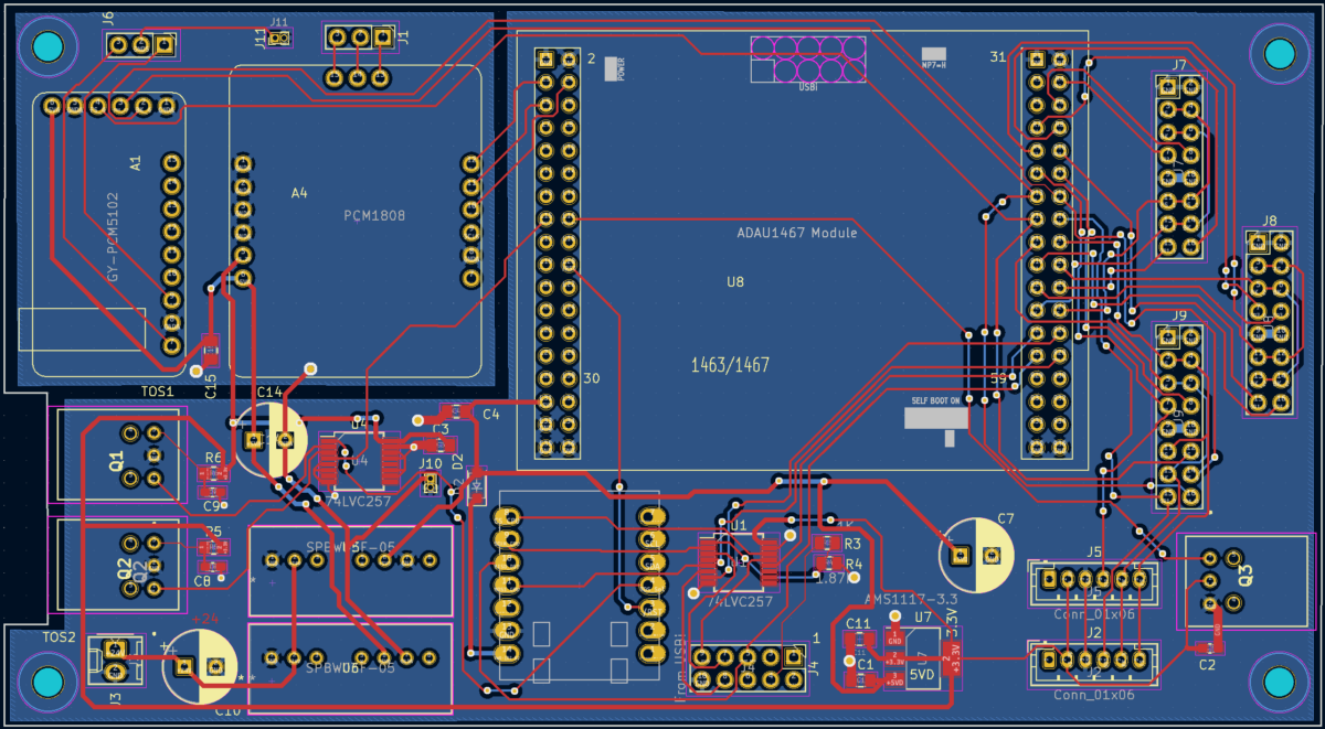
The design will use a CPU board with a socket for the ADAU1467 module and a PCM5102a DAC board for the subwoofer channel. This board with have the connectors to interface to the 3 SSM3582 boards, and it will include some SPDIF I/O with TOSLINK connectors to provide excellent noise isolation.

An interesting variation on this line array CPU/DSP board would only use one of the 8-channel amplifier boards to provide a high quality 3-way stereo amplifier board that would allow me to replace all of those older ADAU1701 designs that are stuck with Bluetooth Classic as the control interface. This newer design will use either Bluetooth BLE or MQTT (Arduino IOT) for control, so the amplifier will function as a “thing” on the internet. The recently announced ESP32C5 looks like an especially good choice for this board, as it will support the much less crowded 5GHz WiFi channels.
This prototype will have two SPDIF receivers: one for connecting to the WiiM mini streamer module, and the other for the SPDIF data extracted from the HDMI PC or TV signal. This provides a very high quality digital audio source, and on a Windows PC the volume of the HDMI audio is controlled by the Windows sound system, so you can use those media buttons on your keyboard for volume level and mute. I don’t have any need for other inputs, but I’ll add a budget ADC board for some backward compatibility.
It looks like the ESP32C5 still has a way to go before being available in the small XIAO or QT-Py format, so this prototype will still use the XIAO ESP32C3. Wondom has a nice TAS5756 stereo amp board with I2S inputs, so I’ll provide their input connector on this board for making a low-cost stereo 3-way system. There is only one DAC, for the stereo subwoofer channel. The board is mostly laid out, but I need to do some more checking before sending it off for fabrication. There is a lot of 3MHz switching going on around those connectors on the right side, where there will be short jumpers to the power amps. I’m hoping the signals will be clean enough at the amps, but that’s what I need to verify with this prototype.

Another motivation for this board is that the last board I made, described in the previous post, did not work well with a single ground plane. That board had 3 DAC’s, and the analog output had a lot of buzzing noise that was due to the radios in the ESP32-C3. I had to cut the ground plane with a razor blade and provide a separate ground to the analog circuitry to keep it quiet. It took a long time to figure out that it was the ESP32-C3 causing the noise, but once the grounds were separated, the board became quiet. Lesson learned.
Leave a Reply