Category: Uncategorized
-
The Marthas
These speakers were started back in 2006 as an attempt to build a fully programmable omnidirectional speaker that could be a 3-way, 4-way or 5-way speaker with any crossover type and crossover frequency. There was a version on display at Dennis Murphy’s house for DIYDC2009 using older technology. However, that earlier technology proved inadequate, and…
-
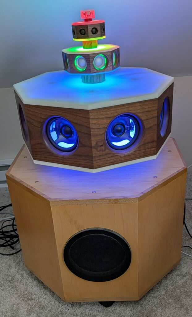
Active Line Array Project
This post announces a new project, the active line array. It is a self-powered constant beamwidth line array designed for serious listening and experimentation. It is portable, easy to tweak for different applications, and it has plenty of room-filling power. Since it also has a built-in streamer and can be used to replace a stereo…
-
Line Array from Hell
Updated Jan, 2026 Sometimes, our experimental projects surprise us by exceeding our expectations, and sometimes they just drag on seemingly forever with nothing in return but frustration and disappointment. The line array using those 8-channel Midiworx SSM3582 boards is clearly in the second group. One of those speakers has been sitting next to my desk…
-
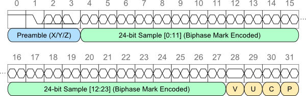
S/PDIF Messaging
Active speakers are a great way to minimize the footprint for home stereo systems, as each speaker has all of the electronics and amplification built into the cabinet, and there is no need for a separate rack of equipment. But this approach has some challenging control issues. Controlling just one active speaker is straightforward, as…
-
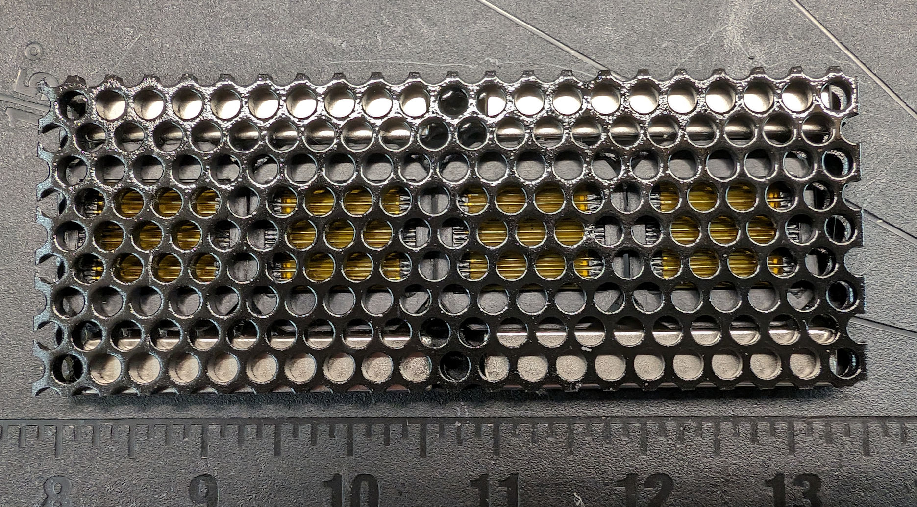
AMT for a Line Array
I needed 48 tweeters to make a 65″ line array, so I came up with a very simple design that I can make quickly. This design uses readily available materials, and it is not overly difficult to construct. I used the small (1″ square) air motion transformer (AMT) diaphragms available at Aliexpress, which are sold…
-
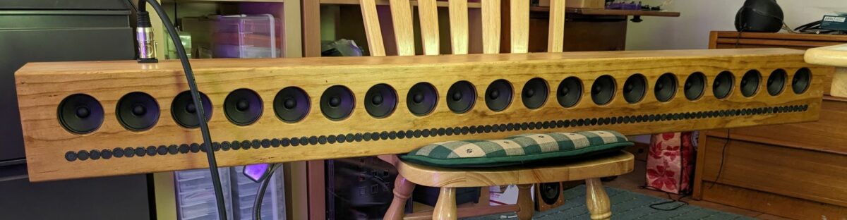
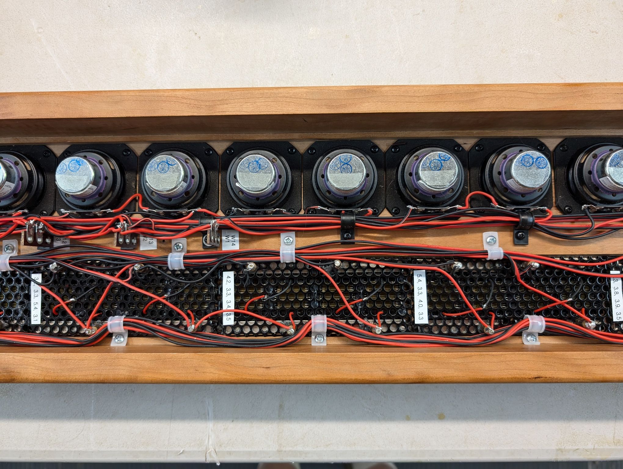
96 Tears
Yep, you are going to cry, cry, cry, cry 96 tears because of all the tweeters used in this project. But, somehow, I got through it, in spite of all the crying, and yes, it was worth it. The picture below is the test setup without the back on for one side. This is a…
-
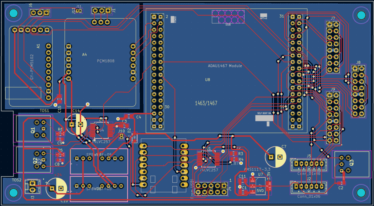
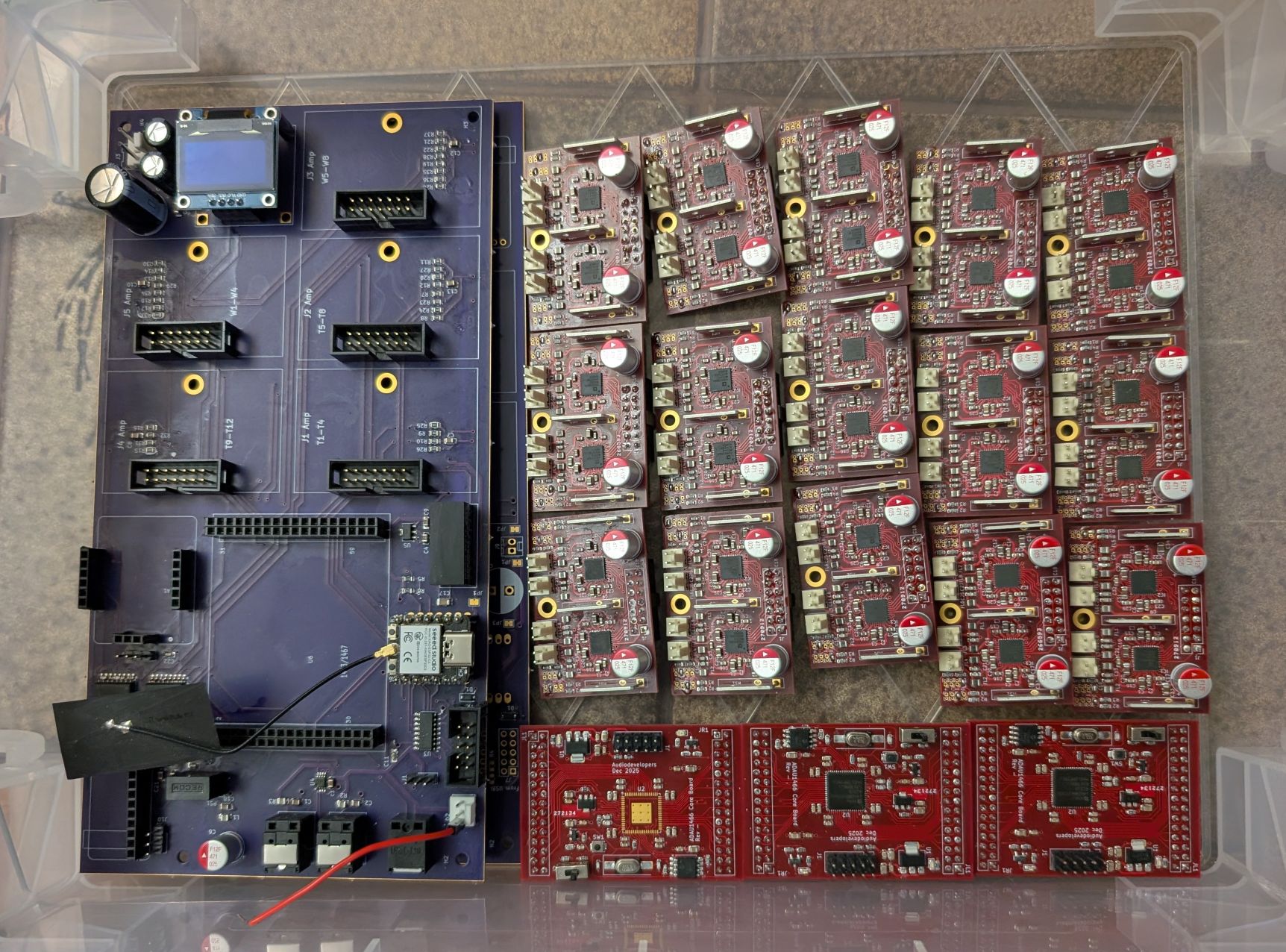
Another prototype (Line Array Amp)
…and an update to the stereo 3-way design I still have some reservations about building the second-generation line array amp described in a previous post, as it requires soldering at least 10 of those 40-pad LFCSP amplifier chips. Those packages are notoriously difficult to solder by hand, and it is way too easy to create…
-
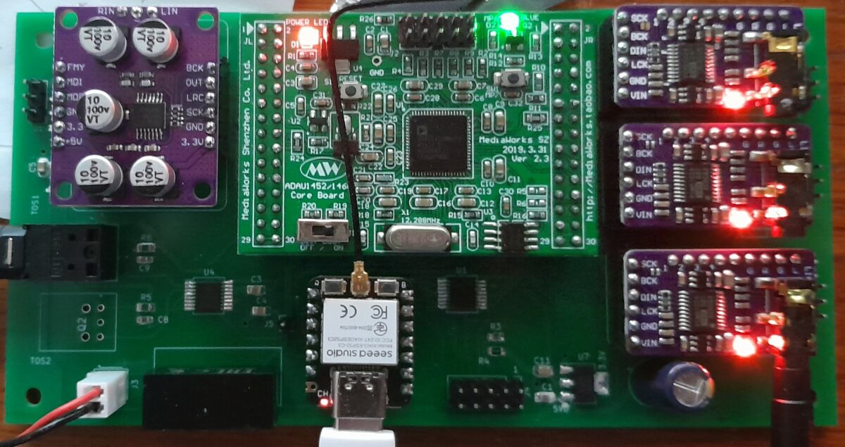
Diversions can be nice
That “diversion board” discussed in the 12/15/2023 post turned out nice. The “motherboard” has two 16-pin SMD chips and a couple of SMD passive components, but it was fairly easy to build. I used socket pins for all the modules, and once you get the hang of mounting them straight on the board, assembly goes…
-
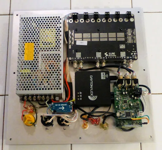
12/15/2023: Another Diversion
The second-generation line array is still in the pipeline, but so is cleaning up some old projects. One that I really liked but needed an upgrade is the “Act 2” active subwoofer with a stereo 3-way plate amp, described in this article. It has two 5-1/4″ subwoofer drivers, with Speakon connectors for the midrange and…
-
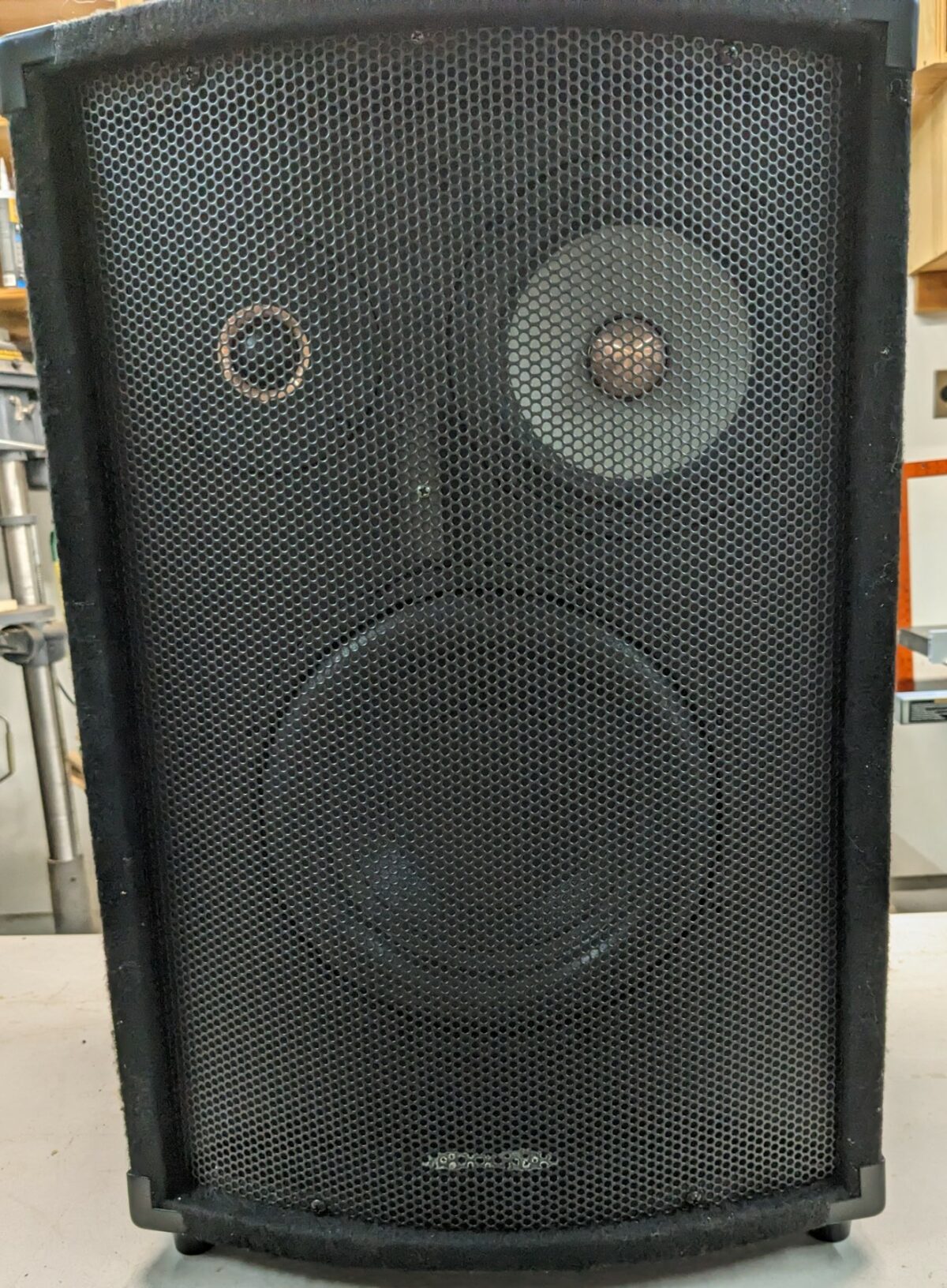
The Russell
Hmmm…what drivers lurk behind that cheap metal grill? And why is the name singular? One of my goals in these retirement years is to use up or dispose of or somehow repurpose a large stash of boards or electronic equipment that I have accumulated during many years of this speaker-building hobby. I’ve got a lot…