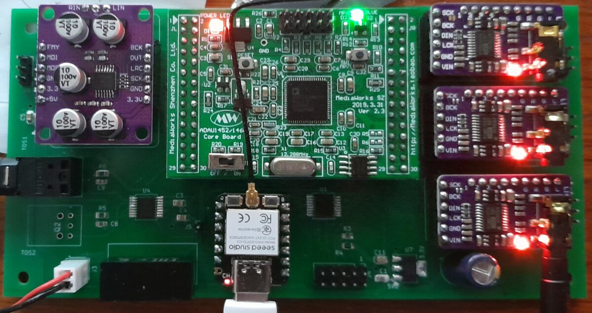
That “diversion board” discussed in the 12/15/2023 post turned out nice. The “motherboard” has two 16-pin SMD chips and a couple of SMD passive components, but it was fairly easy to build. I used socket pins for all the modules, and once you get the hang of mounting them straight on the board, assembly goes quick.

The end product is nice to have in a speaker builder’s toolbox. Add one of those Sure 6-channel amps and you will have a nice stereo 3-way DSP/amp for a PC system. By using one of the 4K HDMI Audio Extractors from Monoprice (product #24278), you can feed this amp from the PC’s HDMI audio using a TOSLINK cable. Windows controls the volume on the HDMI digital output, so you can control the volume using either Windows or an Android or IOS app–that flexibility is nice. With the two SPDIF inputs, you can route audio directly from the PC or else play remotely from a WiiM Mini streamer. Those optical inputs provide perfect electrical isolation, so you don’t have to worry about ground loop noise.

This board can also be used for television audio using the analog inputs. And, because I kept the dipole logic in the SigmaStudio code, it can be used for some interesting open-back speakers. It’s a more versatile design than I originally envisioned, and it is easy to build. The 3-way design doesn’t take advantage of the speed or extra memory of the ADAU1466/ADAU1452, but the newer DSP is still a nice step up from the older ADAU1701 designs. The ADAU1466 provides the SPDIF interface and an array of sample rate converters, so adding “master” digital devices with their own clocks is easy. Also, the ADAU1466 is a lot more responsive due to the faster SPI interface, and the external PCM5101A DACs are much higher quality than the internal ADAU1701 DACs. Those PCM5102A DAC modules are great for the money, but if you want an even better DAC, just change the board layout to use an upgraded module. The Kicad source files are here.
Another upgrade from the older ADAU1701 boards is the use of the ESP32S3. That CPU has twice the memory of the ESP32C3, which allows using the Arduino IOT libraries alongside the Bluetooth BLE control. That’s important because you can develop a single control panel for the DSP and use the Android or IOS app to control the essential features like volume, input, and stored configurations. The IOT cloud tools are somewhat limited in that the individual controls are too big to be used for complicated control functions like specifying custom filters, but they are great for controlling some high-level functions. The Arduino Cloud dashboard for controlling this board is shown below. You can control the DSP from this dashboard on the PC, or you can use the Arduino Remote IOT app on either Android or iOS–they all look and behave the same. It’s an easy way to provide control from an iPhone, although, as noted, the dashboard is limited due to the size and features of the controls. I expect that connectivity to home automation apps will be available soon if they aren’t already, which should add to the fun.
The Arduino CPU can save two different settings, so the Configuration menu allows A/B comparison of two different crossover/EQ settings. Also, you can send the codes documented on these pages using the Messenger control, which will allow control of any feature supported by the micro.

I still haven’t installed this board in the old Act 2 plate amp, since there was a lot of software changes to adapt the 5-way Arduino code for this board. Most of that work is complete, or complete enough that I’m ready to move on. But this diversion proved useful, as I was able to work some more on the Arduino Cloud code and better understand how Windows PC’s control the digital audio outputs via HDMI and SPDIF. Plus, I’ve got both a 5-way and a 3-way configuration of the control software. I don’t think it is practical to develop a “multi-way” code base for both the Arduino and Android environments–it is so much less confusing to have separate programs for 3-way and 5-way designs. The screen shots below show how the Android Crossover screens are different for the two options. The fancy graphing was too hard to implement for a 5-way design, so it got stripped out. The 4 crossovers for the 5-way design makes the HCI rather “busy” (this screen shot was taken before the titles got fixed).

The board design for this diversion only took a couple of hours, so it felt like this would be a quick side-trip. However, the changes to the Arduino and Android code took quite a few days, so it turned out to be a significant diversion, but worthwhile, nonetheless. I’ll probably write this up as a project or article once I get the board wired to amplifiers and speakers. Now, back to those Marthas and the next-generation line array.
Leave a Reply