Active speakers are a great way to minimize the footprint for home stereo systems, as each speaker has all of the electronics and amplification built into the cabinet, and there is no need for a separate rack of equipment. But this approach has some challenging control issues. Controlling just one active speaker is straightforward, as you can simply use Bluetooth or WiFi to stream the audio and send commands to the DSP from a cell phone app. But adding that second speaker is not so easy, as indicated by the red question marks in the picture below.

Bluetooth BLE is a point-to-point protocol, designed to engage one client at a time, and getting the commands to both active speakers is non-trivial. There are some published “mesh” and broadcast solutions that could extend the control to multiple devices, but these are not native to the Arduino Bluetooth BLE libraries.
We could use Wi-Fi to send the control data to both speakers, but in order to use a cell phone app, we need a protocol like MQTT or Matter to build the app and transport the data. The MQTT/Matter solution works well, as both speakers can subscribe to the same published data and be updated at the same time. However, you need to purchase a subscription to a server to implement a MQTT/Matter broker. You can also run the MQTT broker on a local computer, and although I’ve done that in the past, it isn’t the best solution for everyone. I’ve been using the Arduino IoT server, which has been reliable and at $2/month it is affordable, although for that rate you can only have 10 “things” like volume, crossover, EQ, etc. Unfortunately, when I set up the basic IoT control panel I found that I needed more than 10 things, so I would have to subscribe to a more expensive level to continue along this path. Another limitation of the IoT approach is that the tools to implement the Control Panel, or user interface, are still relatively crude compared to what you can do with native Android or IOS code and Bluetooth. Those IoT controls are fine for controlling lights or other simple IoT devices in the house, but don’t work well for more complicated functions like loudspeaker crossovers, electronic curvature, EQ, etc. So, I started to look at other ways to get the commands to both the left and right active speakers.
Another complicating issue for active speakers is getting the same audio data to each speaker. The WiiM audio streamers allow pairing two devices for left and right channels, and the delays between the units seem minimal and stable. That is, these streamers can be used in pairs to create a good stereo image. However, modern homes are starting to have a lot of Wi-Fi devices, from garage door openers, smart appliances, multiple cell phones and computing devices, and it is probably best to look for ways to avoid adding to this Wi-Fi traffic. The approach we are going to consider in this article puts all of the audio and control for the second speaker on a “TOSLINK” connection between the two speakers. It’s no longer a truly wireless active speaker with the fiber connection, but it is a nice compromise of cost, complexity and convenience. The key to making this work is using the User Data bits in the S/PDIF stream to carry the control information from one speaker to the other.

As shown above, the S/PDIF messaging solution only uses one receiver, which can be a streamer like the WiiM Mini. The DSP in the left speaker receives that audio and copies it to an S/PDIF transmitter for the right channel. The DSP also adds the control information to the S/PDIF stream, so we can connect the two speakers with a single fiber-optic cable or coax. This is not truly wireless, as we now have a small cable between the speakers, but it is far less intrusive than the heavy speaker wires and external components of a conventional sound system.
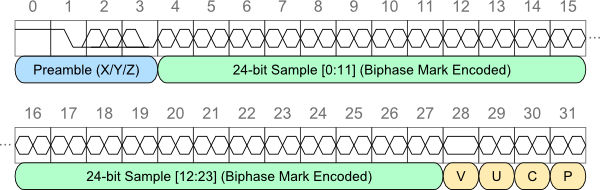
The ADAU1467 has an integrated S/PDIF receiver and transmitter, with registers that allow accessing the Auxiliary Data in the S/PDIF blocks. The ADAU1467 sends stereo 24-bit audio, but each S/PDIF frame is actually 64-bits long. Those “extra” bits are used to send status, parity and validity for each channel, plus “user” data for both left and right channels. For a good tutorial on the SPDIF format, visit S/PDIF Digital Audio on a Microcontroller – scanlime, which is where the featured image for this article was found. The “U” (bit 29) in the image at the top of this blog is the User Data bit in the S/PDIF frame.
The S/PDIF frames are assembled into 192-bit blocks, so that every four milliseconds we can send or receive 48 bytes of user data. This is not a blazingly fast messaging rate, but it is more than adequate for keeping up with changes coming from our cell phone app. Also, it is not a bidirectional flow that we can use to acknowledge the commands, so we need to make sure the data we send is valid.
The ADAU1467 includes hardware to buffer the 192 auxiliary bits per block into 12 16-bit words that we can write to or read from, making it easy to send messages from one ADAU1467 to another. However, it does not have any way to synchronize writing to the User Data, so it is possible that the data could get just partially written into the registers before it gets latched into a buffer for transmission to the S/PDIF stream. To guard against this possibility, we need a simple protocol to send the control data reliably. The protocol is depicted in the state diagram below, which shows the transmitter sending “zeros” until a new command needs to be sent. The receiver discards the first non-zero data it receives, and then accepts the second block, whereupon it waits for the data to return to zero again. The delay on the transmitter side ensures that receiver will see at least one “good” command. This protocol reduces the data throughput to less than 50 milliseconds per word, but this is still much faster than the rate at which a user could send commands from a cell phone. You could also use a CRC check to validate the data, or you could check the data across multiple consecutive frames, but discarding the first non-zero data is reliable, and it is arguably simpler than other methods.

This protocol works well, and it solves the problem of controlling both speakers simultaneously from a single mobile device. So, if you want to change the electronic curvature of your line array and listen to the results in real time, you can do that using this simple S/PDIF messaging. The S/PDIF audio also allows using one WiiM Mini instead of two and ensures less variation in the delays between the left and right audio channels. The “price” is just a fiber optic cable between the speakers that we need to hide behind the furniture.
The final challenge for active speakers is dealing with multiple inputs. The trend now is to just use the wireless streamer to either download music from the cloud or else play music from local network-connected storage such as a media player. Cell phones now offer enough storage to hold fairly large music collections, so this storage can even be taken with you for playback on a wireless speaker. But sometimes you might want to use your active speakers for other sources, such as the television in your living room or a computer. In order to accommodate those external audio sources, we would need to route fiber optic or coax lines from the source to both the left and right speakers. But with the method discussed in this article, all of the input switching can be done in the left speaker, and the selected audio appears on the S/PDIF connection between the two speakers. So, using S/PDIF to route both audio and control information can reduce the number of physical interconnections for active speakers. That’s another SAF positive.
Again, active speakers are a great choice for many applications by allowing us to eliminate those bulky receivers and the audio racks that some wives detest 😏. With S/PDIF messaging we have an effective solution for the major drawbacks of active speakers. There are still some technical issues that haven’t been discussed, such as the coding details and the delay introduced by S/PDIF buffering, but these will be addressed on these pages soon. This messaging was used for the next-generation line array project, and it will probably get detailed in that article.
Leave a Reply