Updated Jan, 2026
Sometimes, our experimental projects surprise us by exceeding our expectations, and sometimes they just drag on seemingly forever with nothing in return but frustration and disappointment. The line array using those 8-channel Midiworx SSM3582 boards is clearly in the second group. One of those speakers has been sitting next to my desk for about a year, and it’s time to get this thing out of my work area for good.
I’ve come to the conclusion that those 8-channel Midiworx SSM3582 boards are cheaply made and that they will not work for a line array amp. The PCB’s are two-layer with fairly thin copper, and the switching noise that rides on the input signals is huge when all channels are simultaneously active. All the channels would work at power on, but the SSM3582 on the leftmost side of the board (near the power connector) would shut down almost immediately and stay that way until the power got cycled. I replaced the board, replaced the chip on that board, and tried beefing up the traces by adding copper wires to the grounds. The only thing that would prevent that one chip from shutting down was removing both speakers connected to those two channels. I had to use three of those boards to get 20 channels for the line array, and that leftmost chip shut down on all three boards. Since each chip provided two channels, I couldn’t just re-route the audio to use the remaining chips, as that would only provide 18 working channels.

The SSM3582 chips on those boards use standalone mode, which means there is no way to monitor fault conditions and recover from them. Also, the line array would intermittently “pop.” Sometimes the popping was very loud and sometimes more like a crackling sound, and sometimes the amps were quiet. I discovered that adjusting the pin drive on the ADAU1467 would make this popping worse, but I was never able to get rid of it. The SSM3582 is compatible with 3.3V and 5V logic, but the switching is based on the internal 1.8V logic, so the inputs are more sensitive to noise than other devices. I tried adding pull-down resistors to each serial data line, and that seemed to improve the popping problem, but the amps would still shut down–it just took a bit longer.
Another unavoidable problem with these amps is that they need to be connected to the DSP using a ribbon cable. I kept the ribbon cables as short as possible, but they had to be around 8″ long to reach all 3 boards. There was just too much noise, crosstalk and/or unterminated wiring to make this interconnection reliable. The combination of noisy PCB’s and noisy interconnections means this approach won’t work reliably. I felt I had put in too much time to give up on this design, but I finally accepted that I wasn’t going to be successful with these amps.
Time for new approach
I had made several 4-channel SSM3582 circuit boards a while back, and I didn’t look forward to soldering 20 of those 40-pin QFN packages to make a pair of line array amps. But it had to be done…
These little amp boards address three problems that made the Midiworx boards unusable. First, they are 4-layer boards with power and ground planes in the middle. The heavier traces reduce noise and are much better at keeping the chips cool.

Second, the boards have the I2C bus brought out to the connector, and there are jumper blocks to set the unique I2C address for each SSM3582 chip. The jumpers allow setting up to 16 chip addresses, and since each chip is stereo, the boards can be ganged to provide up to 32 channels. The boards are configured and then monitored by an ESP32-C3 Arduino CPU. The I2C control bus allows setting the analog gain and the values for the limiter and clipping logic, which is useful for getting the most power out of these amps.
And third, the boards can use either TDM4 or TDM8 as the digital audio interface. The TDM stream is much faster than the separate I2S busses, but the wiring to the board is much simpler and goes straight from the DSP to the amp boards without going through vias.
As shown below, the connections on the motherboard are much shorter, which reduces crosstalk and wiring inductance. There are pull-up and pull-down resistors on the motherboard that terminate the TDM lines into 1 volt, which is a good value for the 1.8V logic used by the SSM3582. And, the motherboard is 4 layers, so that it provides good grounding and a much quieter environment than those ribbon cables. Whereas the Midiworx amps had signals with almost 1 volt of noise, these amps have digital signals that look “clean”.

This amplifier works very well. Each amplifier module has two SSM3582 chips, so each module provides 4 channels. There are a couple of parts on the motherboard that need to get moved around, and some circuitry that I want to add in the next revision, but these prototypes are useable to finish off this line array.
The other problem
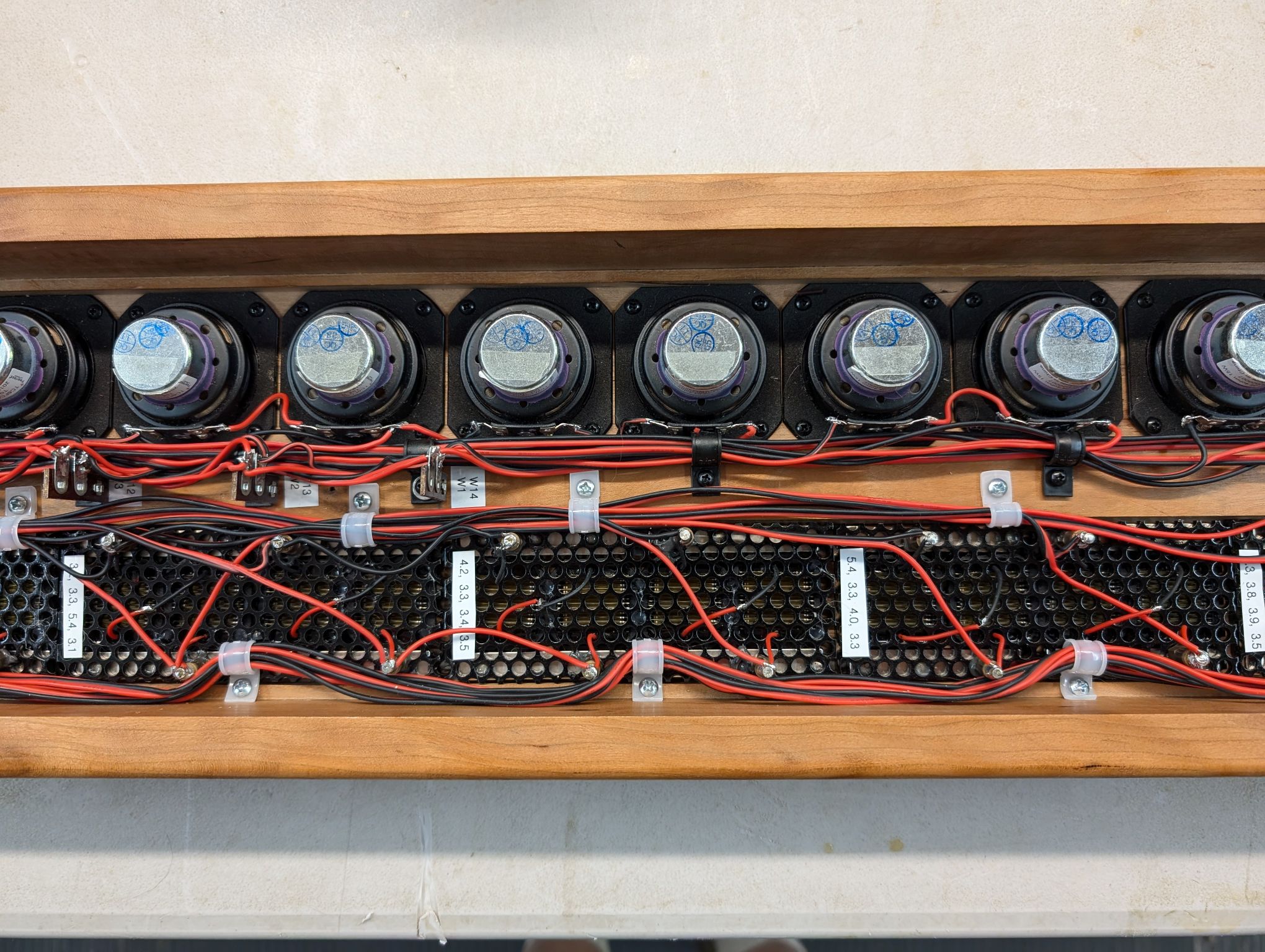
If the only problem had been the amplifiers, I probably would have started on a new design amplifier many months ago. However, what cost me even more time was that the AMT diaphragms had a high failure rate, and even after weeding out the bad ones, they would continue to fail.

The diaphragms are supposed to be 4 ohms, with a DC resistance of around 3.5 ohms. But out of every batch of 4 that I purchased, at least one was open or had some high resistance that didn’t make any sense. The more frustrating problem was that the diaphragms would work for a while and then change resistance value or open up. I got to a point where I was looking for a totally different tweeter solution. However, after many diaphragm replacements I think I might have a reliable set.

Better made diaphragms
For a while in the summer of 2025 those diaphragms were not available on Aliexpress. But then, toward the end of summer, they showed up in a search, at Walmart of all places. I purchased a set of them and all 4 of them tested good, which is something I had never seen before. You can find them with this search at Walmart: “Tweeter Speaker Unit Air Motion”. Then a month or so later, they started showing up again on Aliexpress, but by this time the up-and-down tariffs had taken effect and the shipping cost jumped up from free to around $25 at some vendors. I bought several more of the diaphragms from Walmart because with their free shipping they offered the best price, although as of November 2025 it looks like some of the vendors on Aliexpress have figured out how to get around the tariffs, and shipping prices are now more reasonable. The units now come individually bagged in nice padded black boxes and so far, they have all tested good. There are still some manufacturing variances, with the diaphragms measuring between 3.2 and 3.8 ohms, but overall, the quality seems to have improved enough to say this problem has been fixed. I replaced about a dozen more of the out-of-tolerance diaphragms and I’ve got a stash of replacements if I have more problems in the future. After considerable frustration, I’m now feeling much better about these AMT tweeters for line arrays.

I had only wired up one line array for testing purposes, so I still need to wire up the second array and get this project finally completed. Fortunately, I had been able to get a lot of the software tested, so maybe this line array from Hell will be fully redeemed and sounding angelic in the next few weeks.
Update: And yet another problem…
Replacing those cheaply made 8-channel amplifier boards made a big difference, as already noted. However, it still took a lot of tweaking to get all of the channels working properly using TDM8. SigmaStudio allows changing the output drive current and rise time of each output pin, and after a lot of experimenting, I found that all of the BCLK signals needed to use highest drive, with the SDATA and LRCLK signals set to minimum. Without those settings, the audio had the same popping and random noise that I experienced with the 8-channel Midiworx amp boards. TDM8 multiplexes 8 audio channels onto a single SDATA output pin, so the LRCLK frame rate is 384KHz, which by itself is not an extraordinarily high data rate. However, with 32 bits per frame, the BCLK frequency for TDM8 is 12.288MHz, which is high enough that good board design and extensive decoupling is needed. There are some discussions on the ADI engineer site about proper board design for 192KHz audio, and those discussions included the need for 4-layer boards with good power and ground planes, and extensive decoupling at multiple positions around the ADAU1466 chip.
The Midiworx ADAU1466 core boards claim to use 4-layer boards, “to ensure high SNR signal-to-noise ratio.” However, you can see from shining a light through the back that the ground and power planes are not continuous in all areas (see picture below), so I had some suspicions about these boards. However, after cutting a small section of the board, I was able to verify that the board is 4 layers, although the internal layers appear to be only 1/2 oz copper.
I could get the boards to work by adjusting the ADAU1466 pin drives, but I wasn’t comfortable with that solution, as it was too close to the edge of not working. So, I decided to build my own DSP board with heavier power and ground planes to see if I could increase the reliability.

I used that same circuit and physical layout as the Midiworx board with some minor simplifications. I used a 4-layer PCB design with 1oz copper power planes, thicker top and bottom traces and a bit more decoupling. I looked into having the board assembled at JLCPCB, but the cost would be around $400 for 4 boards. Part of that cost was a $3 fee for loading each SMD part, and since there were 20 unique parts, the loading fee was $60. With US tariffs buried in the shipping cost and with China’s tax, the cost is about twice what it would have been a year ago, and I just didn’t want to spend that much on a prototype board that I haven’t yet tested. I’m not a fan of soldering QFN packages, but I decided to try it anyway and ordered a set of Digikey’s “DKRED” boards (made by Royal Circuits).

The new DSP boards are an improvement over the Midiworx boards, as they require less futzing with the pin drive values to make the audio reliable. However, they weren’t a perfect solution. They could be further improved with ground fills on the top and bottom layers, and I forgot to label the self-boot switch positions.
I doubt that I will ever make any more of these boards, but it is nice to have the design and extra boards available since the Chinese versions have gotten expensive due to the tariffs. Arrow was selling the SSM3582 chips at a clearance price, and I ended up buying enough of them to populate another 10 amplifier boards. So, I’ve got enough DSP and amplifier boards to make a few more line arrays or ring array speakers, should I ever want to do that.
Leave a Reply