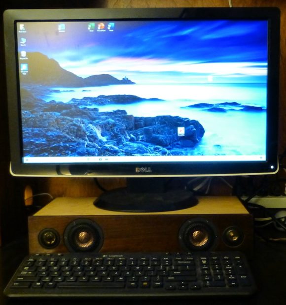
Sadie is one of my sweet granddaughters. We gave her a small gaming computer several months ago, but I only gave her a small “budget” Bluetooth speaker for sound. I wanted to give her some nice speakers, but most of the 3-way designs on these pages were too big. So I wanted to make something that was low-profile and that would double as a stand for her monitor. It’s not really a sound bar because it is intended for near-field listening, so I’m calling it a monitor stand. But it’s plenty loud and it sounds good across the room, so a variation of this design would also work as a sound bar for a TV.
Another reason for doing this project was to test some optimization software that models the bass enhancement options for the stereo 3-way DSP board. So this project was part of an additional software effort that I had already started. Plus, there are a number of interesting challenges with nearfield designs that this project would allow me to explore. I was going to send this out as a Christmas present, but I’m still experimenting with the software.
The Approach
Sadie is tall for her age, but I couldn’t make the monitor stand too tall or else the monitor would sit too high. So I set the maximum height at around 3″, and decided on an 8″ by 16″ shape to give me approximately 3L of total volume. 3L is a bit small for a sealed design and 3″ doesn’t allow for very large drivers, so I decided on using a pair of ND-65 “subwoofers” with their mating passive radiators. Madisound had the 2″ Fountek FR59EXE on sale, so I decided to use a pair of those for the midrange/woofer, along with some no-name tweeters that I had bought years ago.
The Cabinet
In order to maintain that 3″ height constraint, I needed to use 1/2″ lumber throughout. I wanted the cabinet to be as solid as possible with 1/2″ lumber, so I used some very hard Brazilian walnut for the sides and good quality Baltic birch for the top and bottom. The Brazilian walnut was very easy to work with, as it is exceptionally strong yet easy to machine. It cut and routed with no splintering, and it glued together perfectly straight using PL-8 adhesive. I tried using the 1/2″ “white wood” plywood from Lowes for the top and bottom, but that wood is poor quality, as it warps badly as soon as it is cut. I ended up going to Woodcraft for some nice Baltic birch.

The cabinet has a separate sealed chamber for the Fountek driver, and the top is permanently glued to the walnut frame. The electronics are assembled from the bottom.

The Electronics
I got another one of those $25 TPA3116 six-channel amps to go with a stereo 3-way DSP board, along with a nice surplus 65W 24V power supply from MPJA ($10). I wanted to be able to pull out the electronics from the back, so I got some aluminum plate and angle stock from Metal Supermarkets in Beltsville, MD to make a sub-chassis. There is a 12-pin speaker connector to make it easy to remove the sub-chassis.

MPJA also carries some nice airtight strain reliefs for the AC cord–they call them “sealing glands”. I thought they were pretty cool and tried showing my wife my glands, but she just threatened to slap me when I asked her to take a look :).
Something else in that picture above might stand out: the heat pipes. That amp board uses 4 TPA3116 chips, and at 24V, there is a serious amount of heat that needs to get removed from the box. The heat pipes are flat–4mm thick, and they make good contact with the existing heat sink. I used some small brackets to sink the heat to the panel, and that works very well to keep the temperatures at reasonable levels. You can bend the heat pipes by wrapping them around cylindrical objects, but be careful because they can kink easily. They are filled with distilled water, and the water vapor needs to flow throughout the pipe.

The assembled view shows some white heatsink grease on the heat pipes, and I ended up using even more during final assembly. The back panel gets fairly warm, so you know the heat pipes are doing their job. I even added an extra heatsink on the back plate to drop the temperature further.

I had countersunk the woofers and passive radiators to make them look nicer, but I was concerned they might get poked. So I added some grills. They look a bit clunky, but at least the drivers are protected.

Those grills on the woofers are a bit much, but the front has a nice clean look.
Setting up the DSP
The stereo 3-way DSP board has a connector for plugging in a Bluetooth HC-06 module that allows controlling the DSP parameters. There is a nice Android Studio app with multiple pages for controlling the DSP, and that is still the easiest way to set up the DSP. However, the optimization software referenced in the introduction introduces a new control interface for a PC. The larger screen for the PC allows seeing all DSP options on a single page, which is convenient. There are still some unfinished features, such as the frequency response graphs for the Crossover and Bass Boost modules, but all other features are functional, in that you can change the volumes, EQ, Crossover, Delay, and BSC in real time while listening to the changes.

This screen capture was actually for the DSP board in my desktop speakers, but it shows all of the DSP functions available for this project.
Amplifier Mods
An issue with nearfield speakers is that the close proximity of the speakers makes any amplifier noise and hiss problematic. And for this project, the amplifier hiss was simply unacceptable. The board is configured from the factory with the gain set at 32dB, which is a voltage gain of 40. That much gain is nice to have for sources like the ADAU1701 DSP which have a relatively low output, but it also results in very noticeable “hiss”.
There was a thread on diyAudio that discussed the gain of this amplifier and how to change it. One surprising result of that discussion was that there are several versions of this 6-channel amplifier board, and each of those versions had the resistors that controlled the gain in somewhat different locations and orientations. So if you wanted a simple guide for changing the gain of the board, you needed to make sure you changed the right resistors according to which board type you had. The graphic below summarized the 3 different board variants that were discussed in the diyAudio thread. On one of the boards the resistors could be changed with a hot air rework station, but the other two had tight component placement that made it easier to use a soldering iron. The resistors that get changed are 0603 size, so it takes a good temperature-controlled iron with a fine tip, stainless steel tweezers, magnifying lenses and steady hands to change the gain.

I changed the gain of the tweeter and mid/woofer channels from 32dB to 20dB, and the hiss is no longer objectionable. I also changed the sub channel to 26dB gain. With these gain changes, the speaker is still quite loud at full volume, and the drivers are close to their maximum excursion. However, the amplifier can’t be driven to it’s maximum output, because there isn’t enough gain. So those fairly powerful 50W amps aren’t being used to full capacity. In hindsight, it would have been better to use a lower voltage for the power supply. The lower voltage would still have provided plenty of output, and there would be less heat generated. So next time I’ll use 18V or so for a nearfield monitor. But the 24V supply is best if you are trying to fill a room with sound.
Measurements and Tweaks
–This section under construction
Final Thoughts
–This section under construction