This project starts with a warning: because of the way the Sure JAB3-250 is designed, there are some unusual steps you must take to use this interesting board as a 2-way amplifier for an active speaker. The board uses a microprocessor to monitor the audio input and shut down the DSP when no signal is present. While this is a great feature for battery operation, it gets in the way of using the board for active speakers. The solution described in the first part of this article requires some soldering to the board and/or changes to the code in the on-board microprocessor. Those modifications will void your warranty, and it makes what was hoped would be an exciting project into something that isn’t so cool. There is a more elegant solution described in the Postscripts, and that solution has been tested on the newer JAB4 board. That solution hasn’t been tested with the JAB-250, although the changes needed to make it work should be minor.
The intended application for this project is TV speakers that could double as WiFi room speakers.
Overview
The JAB-250 is the Sure Electronics 50W/50W amplifier board with built-in DSP. And yes, the DSP is the ADAU1701, for which there is a lot of information and software already available in these pages. So, on the face of it, this board looks ideal for building active speakers. But as it turns out, there are some serious “gotchas” that make the effort much more difficult than I expected from an initial assessment. However, there is some good potential for using the Sure board if someone can come up with a better solution than I did for dealing with the peculiarities of the Sure board, so it’s worth documenting this project. Also, this project only explores using the Sure board as a 2-way design, but there are additional outputs that should allow simple expansion to a 3-way design, using the non-DSP Sure amplifier for the woofer/subwoofer channel. The 3-way option isn’t explored in this project.
The project used some cabinets and drivers that I purchased about 15 years ago, back when I was working with the TAS3004 DSP. Each speaker already had a plate amp that I had made with a TI evaluation board with the TAS3004 and a 25W stereo class D amplifier. It looked like I could update the plate amp fairly easily, so this looked like a good opportunity to evaluate that Sure DSP amplifier board, integrated with a WiFi adapter.
The drivers were the Morel HU631 and Hiquphon OW1. Because of the Morel and Hiquphon nameplates, and because I generally don’t use fancy names for speakers on these pages, I should probably call these speakers the “More Hickies”. But “JAB-250 WiFi” is fine.
The Design
Since I already had a chassis for mounting the electronics and drivers mounted in a decent cabinet, this project focused on wiring and software modifications. The block diagram below shows the components that needed to be wired together:

The Sure amplifier includes the ADAU1701 DSP chip and a microprocessor, but the microprocessor is not “connected” to the ADAU1701 via the I2C bus. The board has an EEPROM for holding the code for the ADAU1701, but once self-loading is complete, we can take control of the ADAU1701 via the I2C bus with our own CPU. The I2C connection is simply two wires, once the common ground connection is made.
The power supply should be around $25, and there are many sources for low-cost DC-DC “downconverters” that can output 5V at .5A. I used an adjustable LM2596 board that was less about a dollar each in a set of 5 pieces. The 5V to 5V isolation module will ensure that there is no noise pickup through the shared grounds of the WiFi and amp. You can get a 2W or 3W isolation module for about $8 at Digikey or Mouser.
The teensy3.2 board has plenty of “horsepower” and code space to run the code that is described elsewhere on this web site. For this design I just used the Nextion display because I has some that I had already purchased, but you can also use your cell phone with a Bluetooth adapter to task the teensy3.2. At one time I had both the Bluetooth adapter and the Nextion display connected at the same time, but decided to reuse the Bluetooth modules for a different project.
The WFA02 module needs to be modified slightly to ensure a good WiFi signal. You will need to unplug the existing strip antenna and use a U.FL to SMA adaptor to allow using an external antenna. You need to be careful when purchasing the adapter to make sure you get the right polarity for the antenna, although there are many “kits” on eBay that include both the cable and the antenna, already matched.
WiFi
As already noted, the WiFi is implemented using two of the Dayton WFA02 modules, one in each cabinet. The WiFi app allows syncing the two modules and selecting whether to use the left or right channel for each speaker. That way, there is no wiring between speakers–all of the channel routing and synchronization is done inside the modules, under control of the Hi-Fly cell phone app. Using two WiFi modules increases the cost of the project, but the added flexibility is worth the expense.
Each WiFi module has an analog input, and those inputs are brought out to RCA connectors on the plate amp panel. You can plug an analog source such as a TV into either speaker, and the one that is the master will transfer the audio via WiFi to the other.
Wiring Pictures

The plate amp isn’t too complicated, but it took some careful routing to make the wood enclosure for the Nextion LCD display.

The power supply is on the other side of the panel that holds the amp and WiFi module.

The picture below shows the WFA02 U.FL antenna connector on the lower left corner of the Linkplay A31 module. As noted earlier, using an external antenna rather than the small strip antenna buried in the box will result in a much more reliable connection to your home router.

The Power-down Problem
The reason why this project turned out to be more difficult than I expected is that Sure optimized the board for battery operation. There is a microprocessor on the board that is there solely to manage power consumption. The microprocessor monitors the audio activity using one of its on-board A/D converters, and when there is no audio input, it shuts down the ADAU1701 chip. This shut-down is important for extending the life of the battery, but it creates havoc for the DSP software that is described on other pages on this web site. When the audio is resumed, the microprocessor resets the ADAU1701, and it reloads the program in the EEPROM connected to the I2C bus for the ADAU1701. However, it also resets all of the Parameter RAM data that our software has loaded into the DSP. So all of our volume, crossover, EQ and other data gets wiped out by the power management logic when the board comes out of low-power mode.
There are a couple of ways to solve this power-down problem, but I chose the “brute-force” approach, which is to disable the low-power mode by reprogramming the Sure microprocessor. I had to buy a PIC programmer and download the PIC software tools, but the programmer is cheap, the software tools are free, and it only took about 10 lines of very simple code to disable their micro. A more elegant solution would be to use our own CPU to monitor when shutdown occurs and reprogram both the program and parameter data of the ADAU1701 when the power was restored. That approached would be a better and easier to implement solution than just disabling the on-board micro. However, I was having problems with the boards self-destructing, and on one of the boards that died, the protection diodes for the I2C signals shorted out. I had already burnt out two of the JAB-30 boards and lost the patience to come up with a better solution. But I would certainly encourage others to follow up with trying to write code to work with the existing power-down logic–that would make this project much better.
The code to disable the Sure micro is very simple. I added some additional code to flash one of the two orange LED’s on the board to verify that the micro was reprogrammed, but that really isn’t necessary. All of the pin names such as IO_RC1 are defined by the Microchip MPLAB X IDE when you select the PIC16F1503 chip as the target. I used the kit 3.5 programmer that is about $15 on eBay. There is a 5-pin outline on the Sure board for connecting the programmer, but the pads use 2mm spacing rather than the .1″ spacing of the programmer. So you will have to use needle-nosed pliers to bend the leads of a 5-pin .1″ header to attach to the board. Yep–this isn’t a good solution, but it’s all I have right now. Here is the PIC code:
void main(void) {

	SYSTEM_Initialize();

	IO_RC1_SetLow(); 	//ADAU1701 Voltage Control
	IO_RA1_SetHigh(); 	//Mute
	IO_RA0_SetHigh(); 	//reset

	delay_sec(1); 		//Wait 1 second
	IO_RA1_SetLow(); 	//unmute
	IO_RA5_SetHigh(); 	//unmute preamp audio

	delay_sec(1); 		//Wait 1 second
	IO_RA0_SetLow(); 	//un-reset and enable amp

	while (1) {

		IO_RA4_SetHigh(); 	//LED off
		delay_sec(3);
		IO_RA4_SetLow(); 	//LED on
		delay_sec(1);

	} 	//flash LED forever
}
Partial Schematic of the Sure Board
I needed to partially document the schematic in order to understand how to disable the power-down feature. The schematic below is from manually tracing, which is hard to do with double-sided SMD boards, and it may have errors:

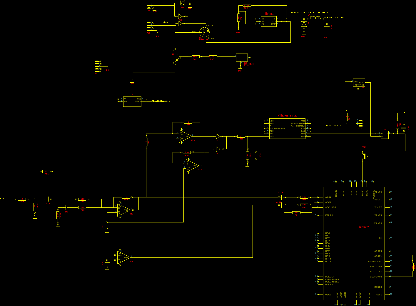
After tracing the circuitry, it became clear that an alternative to reprogramming the micro was simply to “short out” Q1, which is the transistor used to remove power from the ADAU1701 (duh!). Q1 is on the top of the board, under the heatsink.
Software Modifications
There are three issues with using the software developed for the stereo 3-way board. First, the Sure board doesn’t use the same channel assignments as the stereo 3-way board, so I needed to make some changes to get the high frequencies to the tweeter amps and the low frequencies to the woofer amps. These changes are fairly simple and are confined to the Arduino code, and the code has been updated to correct the channel assignments.
A more complicated issue is that the user interface is designed for a stereo 3-way system, yet the speaker is actually a two-way mono system, where one speaker is the left channel and the other is the right. And yet another issue is that there are a number of nice bass enhancement features that are available for the subwoofer, but there isn’t a subwoofer channel in this project. The features could be added to the woofer channel, but would require extensive changes to LCD user interface, with some corresponding changes needed in the Arduino code.
If the Sure JAB3-250 board had turned out to be easier to use for making 2 or 3-way speakers, I would have made these user interface and embedded code changes, as this board would be a great low-cost solution with tremendous flexibility. However, the fact that we need to modify the board makes the Sure board much less attractive, so the decision was made to use the user interface “as-is”. The LCD display works fine with the volume, crossovers and EQ, and the special filters work properly. You can select from a number of crossover types and crossover frequencies, set individual driver volume levels, and provide overall EQ to the system. That’s good enough to accomplish the tweaking needed to achieve good audio from these speakers. There are a number of buttons in the LCD user interface that don’t do anything, but that’s not going to change for this project. If someone can help me find a way to use the Sure board without making modifications, I’ll consider finishing off the Nextion user interface code and the associated cell phone app.
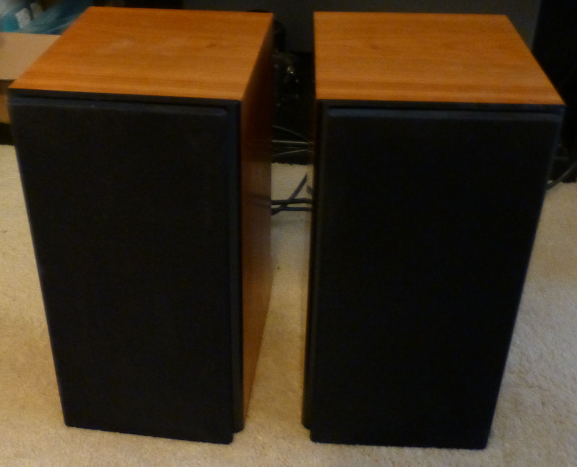
Drivers and cabinet
As noted in the overview, the cabinets and drivers were re-purposed from an earlier project. The drivers are high quality, and they sound good. The OW1 tweeter and the Morel HU631 are “well-behaved” in that the frequency response is relatively smooth, so there are a number of crossover frequencies and slopes that can result in good overall sound, and extensive EQ is not required.
The cabinets were pre-fab boxes from either Madisound, PE or Meniscus, but it’s been so long ago that I can’t remember the source. They are about 13L and sealed, which results in an F3 of 100Hz and an F10 of 45 Hz, which is probably OK for the intended application. The boxes can be used with a subwoofer, although right now the subwoofer signals are not brought out to connectors on the plate amp. The stereo 3-way software has a number of bass boost and enhancement algorithms that are available on the subwoofer channel, but with some simple modifications these bass processing features could also be available on the channels routed to the Morel woofer. If additional bass extension is needed, I’ll make those modifications.


Conclusions
The speaker works well and it sounds nice, but the JAB3-250 board turned out to be difficult to use. The Sure board is optimized for battery operation, and those optimizations get in the way of our attempts to use the board as the heart of a simple, low-cost 2-way amp programmable board for active WiFi speakers. It’s possible to disable the power management features that get in the way, but it takes some brute-force software and/or hardware modifications to make that happen, and the changes will void the warranty.
There is a possibility that our teensy3.2 CPU could monitor the power-down operation of the Sure board and reprogram the ADAU1701 when power is restored. That would be a more elegant solution that might not require modifications to the board, but the author ran out of enthusiasm for this design before that approach could be implemented. The solutions proposed in Article 6 on this website for the Revision 3 or 4 boards seem like a better approach.
Postscript, after thinking about project a bit more…
Another possible solution to the power-down problem is to write code that would save the Parameter RAM information for volume levels, crossover filters, etc. into the self-boot EEPROM on the Sure board. That way, when the ADAU1701 got reset after a power-down, both the code and the parameters would get restored. The code isn’t that tricky, as the format for the self-boot EEPROM is documented in the ADAU1701 datasheet, and there is already code available for reading the EEPROM data. If there is adequate interest the author might pursue this solution.
Postscript #2 (about two years later)
The article on Mom’s Bluetooth Garden Table describes the solution outlined in the first postscript. The solution is to store the ADAU1701 program in the external EEPROM and update the Parameter data in the EEPROM whenever changes are made from the LCD display or cell phone app. When the ADAU1701 is rebooted, it loads the program and updated parameters from the EEPROM using the self-boot feature.
This solution created a new problem. Because there is no arbitration for the Parameter RAM in the ADAU1701, whenever you read that memory from the I2C bus, it disrupts the DSP’s access to that data. As a result, there is a lot of popping and weird noise whenever you read the data with audio playing. If you try to mute the device before reading the Parameter RAM using one of the cells in the SigmaStudio design, it will save that muted state in the external EEPROM, and when the ADAU1701 reboots, it will come up muted. The only other way to keep the chip silent during reads is to mute the intenal DAC’s using the Core Control Register. We also need to add a message in the external EEPROM to restore the Core Control Register to re-enable the internal DAC during self-boot. This works fine for 2-way boards, although a 3-way board using an external DAC would require a different solution.
I haven’t actually updated the code for this JAB-250 project with this power-down solution, but it works fine on the JAB4 board. I might come up with a variant of the JAB4 code for these two-channel boards at some future date, since the changes required to adapt this solution to the JAB-250 are minor. The JAB4 design also updated the Nextion display code and redesigned the SigmaStudio code to route the woofer channel through the bass enhancement algorithms.
This new code could be useful for building TWS Bluetooth 2-way active speakers with the JAB-250. The QCC3008 chip from Qualcomm is used in many readily available Bluetooth boards, and it supports TWS (True Wireless Stereo). With two of those boards, one in each speaker, and with a JAB-250 board in each speaker, you can have a nice stereo active speaker system with many Bass Enhancement features. The QCC3008 requires some external switches to force it into TWS mode and to pair the chips, but it is not difficult to use. I’ve already got some TWS active speakers using LM3886 amps, so I probably won’t document a JAB-250/QCC3008 active speaker with Bluetooth TWS. However, if someone wants to write up their design, I’d be happy to add it to these pages.