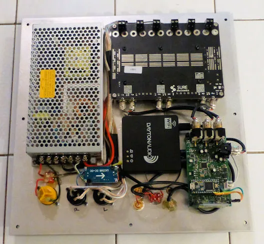
12/15/2023: Another Diversion

The second-generation line array is still in the pipeline, but so is cleaning up some old projects. One that I really liked but needed an upgrade is the “Act 2” active subwoofer with a stereo 3-way plate amp, described in this article. It has two 5-1/4″ subwoofer drivers, with Speakon connectors for the midrange and tweeter outputs. I like this arrangement, because I can use it to test different mid/tweeter combinations, and it is a nice setup for PC audio. I’ve got two mid/tweeter cabinets already (one of which I’ve never really listened to) and I wanted to be able to test some other combinations of drivers I have laying around. The existing plate amp uses some older circuitry, with the ADAU1701 for analog I/O, a teensy CPU with “classic” Bluetooth for control, and one of the older Linkplay modules for WiFi. I want to use the newer BLE or MQTT control interfaces and I want to use the newer WiiM Linkplay module to use the much less crowded 5GHz WiFi band.

What I wanted to save from the original design was the chassis and the amp board, which I had modified to use film output filter capacitors. The chassis and amp were a big investment in time, and even though I would have preferred a newer amp with an I2S interface, this older 6-channel amp was still “good enough”. The inside of the original 6-channel plate amp is shown below.

The replacement for the 2×6 ADAU1701 board, in block diagram form, is shown below. I wanted to go with optical connections to avoid ground loop issues, but I’m also using an analog input board to provide more flexibility. The ADC board was about $3 on AliExpress, and the DAC boards are about $4 each. It’s a bit silly to try putting that circuitry on the board yourself, given those low prices for the modules. The circuit board ends up being a “motherboard” for interconnecting the modules, with all the modules using sockets. The only other components on the board are the SPDIF receivers, some multiplexer chips, some decoupling capacitors, a voltage regulator, and 4 resistors. That “switch” for the SPI interface allows control from either SigmaStudio or the micro. It uses the voltage from the SigmaStudio programmer to control the multiplexer, so you can load the code from SigmaStudio and then unplug the programmer and revert to control by the ESP32.

The draft layout is shown below. I’ll send this out for fabrication in the next few days. I had all of the library parts already in Kicad, so the PCB design came together fairly quickly: