Crossover Equations
This overview describes the math that is used to model the crossover. This information is provided to help the user understand the results and to perhaps “demystify” the crossover module.
Woofer Equations
Only the woofer section is discussed, as the concepts are easily extended to the other drivers.
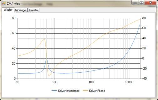
Before diving into the circuit equations, we need to understand how the crossover interacts with the driver. The driver itself can be thought of a complex circuit of mechanical and electrical components. This “driver circuit” has an output that is related to the input that we can measure—this is the “FRD” response file. Also, the driver has a complex impedance that we can measure—this data is in the “ZMA” file. If you look at a typical impedance and phase curve, such as the one in the chart below, you can see that the impedance is not constant. The manufacturer’s rated impedance is usually a value that is somewhat higher than the lowest point on the blue curve in this chart, and although that number may be useful for selecting an amplifier, it is not adequate for designing the crossover. The variation of response and impedance with frequency is why simple crossover calculators typically result in poor sounding crossovers.
The Crossover module uses the response and impedance data (FRD/ZMA files) to calculate the actual voltage at the driver at all frequencies. Since this module resamples the data to 500 frequency points, the crossover calculations are repeated 500 times for each driver. So as you adjust the component values for the crossover, you are repeating the calculations described in the next section 500 times for each driver.
Woofer Circuit
The schematic for the Crossover module is shown below. As indicated, there are 4 voltage nodes: Vin, V1, V2, and Vdriver. Also, there are 8 impedances: Z1, Z2, Z3, Z4, Zs1, Zp1, Zp2 and Zdriver. A simple way to deal with this schematic is to think of it as a series of voltage dividers. The best way to determine the voltages at each node for this topology is to work “backwards”, starting with Vdriver. But first we need to calculate the impedances for each group of components.
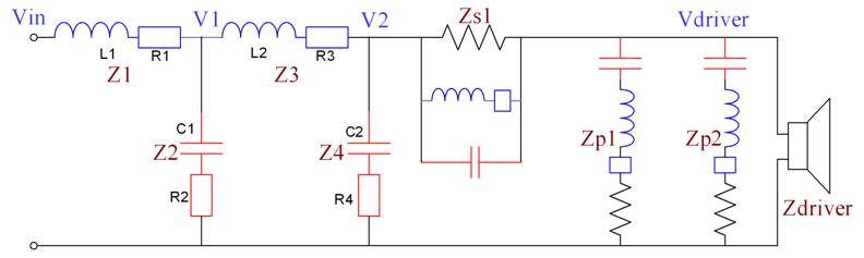
The impedances are easiest to work with using the s-plane complex number notation (Laplace transforms), where the impedance of the inductor is sL, the impedance of the capacitor is 1/sC, and the resistance is R. The first 7 impedances in our list are:
Z1 = sL1
+ R1
Z2 = 1/sC1 + R2
Z3 = sL2
+ R3
Z4 = 1/sC2 + R4
Zs1 = 1/(sCs1 + 1/(sLs1+Ls1_DCR) + 1/Rs1), where Cs1, Ls1, Ls1_DCR, and Rs
are the components in the serial impedance Zs1
Zp1 = 1/sCp1 + sLp1 + LP1_DCR + Rp1, where Cp1, Lp1, Lp1_DCR, and Rp1
are the components in the parallel network Zp1
Zp2 = 1/sCp2 + sLp2 + LP2_DCR + Rp2, where Cp2, Lp2, Lp2_DCR, and Rp2
are the components in the parallel network Zp2
The last impedance to consider is Zdriver. We know what this is: it is the data in the ZMA file, which
tells us the impedance of the driver at each frequency.
Now calculate the parallel impedance of Zp1, Zp2, and Zdriver, and call it Zpdriver:
Zpdriver = Zdriver
|| Zp1 || Zp2 = 1/(1/Zdriver +
1/Zp1 + 1/Zp2)
Zs1 is in series with Zpdriver, so:
Zspdriver = Zs1 + Zpdriver
OK, here is the first voltage divider:
Vdriver = V2 * Zpdriver
/ Zspdriver
Continuing
to work toward the input of the circuit:
Z4spdriver
= Zspdriver || Z4
= 1/(1/Zspdriver
+ 1/Z4)
Z34spdriver
= Z3 +
Z4spdriver
And
here is another voltage divider:
V2
= V1 *
Z4spdriver / (Z3 + Z4spdriver)
Now
add in the final impedances:
Z234spdriver
= Z34spdriver
|| Z2 = 1/(1/Z34spdriver + 1/Z2)
Z1234spdriver
= Z1 +
Z234spdriver = amplifier load
And
the final voltage divider is:
V1
= Vin * Z234spdriver / (Z1 + Z234spdriver)
Calculating the Response
The equations in the previous section are all that is needed to calculate the response. We can set Vin to be any arbitrary value, and that will allow us to calculate V1. Then we can calculate V2, and finally Vdriver. Once we know Vdriver, we just multiply by the driver “transfer function,” which is the data in the FRD file. Of course, we need to do these calculations for every frequency. The PSD program uses 500 logarithmically-spaced frequencies from 10Hz to 20KHz, so these calculations are repeated 500 times, every time a component is changed. The result is an array of complex data that we can convert to magnitude and phase using the complex math functions.
Notice that the impedance seen by the amplifier for this leg
of the network (woofer leg in this example) is “Z1234spdriver.” The total load to the amplifier is the
parallel combination of the woofer, midrange and tweeter legs.
Notes about the Design
It’s interesting to see how much of the code in the Crossover module is “math” versus code that processes the user-entries. The math is not very many lines of code—it can all fit on a single printed page. On the other hand, the event handlers to accept data in the textboxes, check for errors, adjust values to avoid dividing by zero or to respond to the mouse wheel takes up many, many pages. The math to add another driver in the code (to design 4-way speakers) would be relatively simple, but writing the code for the additional text boxes would take quite a while. This is also true about adding more parallel or series networks: easily done in the math, but time-consuming to change the schematics and write the code for the event handlers. There are no plans at the current time to add more circuitry to the schematic or to support designs greater than 3-ways. However, there is nothing in the program design that precludes these enhancements for a future iteration—in fact, the data model is already defined for a 5-way system.