BOX And BAFFLE MODULE
The Baffle module allows the design to specify the shape of the baffle and the driver positions to determine the effect of the baffle on the overall response. It also provides a calculator for determining the volume of cabinet. As indicated by the arrows on the Workflow Module, these tools should be used early in the design flow. The results of this module are added to the driver response in the “System Response” module.
Box And Baffle Module Form
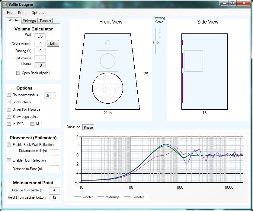
The Box and Baffle window consists of 7 areas:
· Menu Items
· Box drawing
· Driver Tabs and Volume Calculator and Offsets
· Options
· Placement
· Measurement Point
· Charts
The textboxes are designed to be easy-to-use with the mousewheel functionality that is used elsewhere in the program. Simply click on the value and turn the mouse wheel to select the next closest entry in a list of standard values.
Menu ITems
There are 4 menus:
· File
· Print/Save Image
· Help
File Menu
The File Menu allows saving the results of the baffle response to a file in the “FRD” format. This FRD file consists of 500 rows with frequency, amplitude and phase data separated by spaces. There is no header or trailing data, and each row is followed by a carriage-return line-feed combination.
This menu will allow saving the results of each driver, and the number of drivers that appear on the menu list depends on the system configuration (e.g. woofer, 2-way or 3-way).
Print/Save Image Menu
The Print Menu is the same as used throughout the program, with options to print the entire window or to save the charting information to a jpeg file.
Help Menu
The Help Menu provides access to this help file, along with a separate file that provides details on how the diffraction model is implemented.
Box Drawing
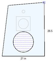
The Box Drawing area consists of an interactive front view, an interactive side view and a Drawing Scale slider control. The front and side views depict the box outline. The box is defined by the corners and sides, which can be moved with the mouse. Simply move the mouse over the corner until the side or corner is highlighted, and then drag the corner or side. Moving the corner will drag the sides along with it. Moving the side will “straighten up” the side as you move it, so that it will be either vertical or horizontal (not at an angle). The following picture shows the upper right corner highlighted.
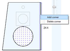
Corners can be added or deleted by selecting a side and clicking the right mouse button. A context menu will pop up as shown in the figure below. Once the corner has been added, it can be moved around. The program allows adding corners until there are a total of 20 corners, so it is possible to create some rather complex shapes.
 The
next figure uses 12 corners:
The
next figure uses 12 corners: 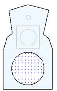
As the figure gets resized in the front view, the side view will follow the top and bottom outlines. Similarly, changing the height of the side view will force the top points of the front view to follow. The box interior changes to yellow when the ratio of the height-to-side on the front view is equal to the “golden ratio,” or 1.62. The side view changes to a yellow interior when the height to depth ratio is 1.62. The golden ratio is often used as a standard for aesthetically pleasing proportions.
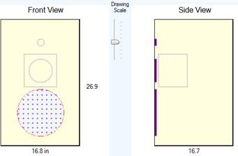
The Drawing Scale slide can be used to scale all dimensions without changing the sides. Simply slide it up and the box will become “bigger”, as can be verified by the numbers for the height and width.
The drivers can be moved around on the baffle or resized using the Box Drawing area. However, the driver must be selected first by clicking on the appropriate tab in the Volume Calculator area. The selected driver will change from gray to a solid outline. The driver can be moved around by clicking on the interior of the driver and dragging it. Clicking on the driver outline will allow you to change the driver diameter. The driver outline changes colors to help show whether the cursor is on the perimeter or interior of the driver outline.
For 3-way designs there is a box for the midrange, and this box can be resized by dragging the sides. The interior volume of the midrange box will be used to calculate the midrange low frequency response, and the exterior will automatically be deducted from the volume of the woofer box.
Driver Tabs and Volume Calculator and Offsets
This area of the Box and Baffle Module is multi-purpose. First, it has the driver selection tabs that are needed to move or resize the drivers. Second, it displays the volume for the main enclosure or the midrange box. When the “Show Interior” checkbox is clicked, the program shows the outline of the enclosure interior, using the thickness that is shown in the Wall Thickness textbox. It’s that interior path that is used to calculate the volume. The volume calculation is actually quite accurate, as it uses a summation of very thin rectangles that track the interior wall dimensions. The textboxes for Bracing and Port Volume allow adjusting the calculated internal volume. Sometimes the bracing materials and port can take up a significant percentage of the overall volume, so in those cases some good estimates for these values will be needed.
The final purpose of the Volume Calculator area is to show the measurement offsets from the baffle. This information is displayed on the Tweeter tab, as show below:
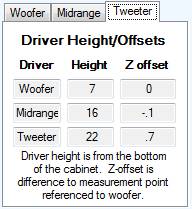 The Z-offsets are the calculated relative
distances of the frame of the driver to the measurement point. You can add a “tilt” to the
baffle by moving a corner in the side view, or change the measurement height to
see the effect on the relative distance.
These calculations are automatically added to the Crossover Module when
its Baffle checkbox is selected.
The Z-offsets are the calculated relative
distances of the frame of the driver to the measurement point. You can add a “tilt” to the
baffle by moving a corner in the side view, or change the measurement height to
see the effect on the relative distance.
These calculations are automatically added to the Crossover Module when
its Baffle checkbox is selected.
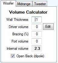 A
feature that may look a bit out of place is the “Open Back”
checkbox. When this box is checked,
the volume calculation is disabled and the ray-tracing program uses additional
rays from the back of the driver.
This box is associated with the driver tabs because the woofer and
midrange can be specified as “open back” individually—that
is, one driver can be open back whereas the other is not. As noted in the Help file for the
Diffraction Model, the ray-tracing calculation is only valid at a single
measurement point and under ideal conditions with no other room, floor or
furniture reflections. Therefore,
this checkbox should only be used with the understanding that the modeled
results are only a partial view of the response, and that many other factors
and other measurement points need to be considered to properly predict the
overall room response of a dipole loudspeaker.
A
feature that may look a bit out of place is the “Open Back”
checkbox. When this box is checked,
the volume calculation is disabled and the ray-tracing program uses additional
rays from the back of the driver.
This box is associated with the driver tabs because the woofer and
midrange can be specified as “open back” individually—that
is, one driver can be open back whereas the other is not. As noted in the Help file for the
Diffraction Model, the ray-tracing calculation is only valid at a single
measurement point and under ideal conditions with no other room, floor or
furniture reflections. Therefore,
this checkbox should only be used with the understanding that the modeled
results are only a partial view of the response, and that many other factors
and other measurement points need to be considered to properly predict the
overall room response of a dipole loudspeaker.
Options
The Options area allows specifying the amount of round-over, some drawing and calculation options, and the units selection.
The Roundover Radius checkbox and textbox specifies whether the calculations should assume reflections from a rounded edge, and how much roundover there is. The roundover calculation is described in the Help file for the Diffraction Model.
The “Show Interior” checkbox is self-explanatory—it shows the interior of the woofer and midrange boxes in dotted lines. You can select different wall thickness values to see the effect on the interior dimensions.
The “Driver Point Source” checkbox simplifies the ray tracing algorithm by treating the driver as a single point rather than multiple sources at ½” spacing. This option is useful for understanding the effect of driver size on diffraction, but typically this checkbox should remain unchecked.
The “Show Edge Points” checkbox is simple there for the technically curious who want to see the illumination points used for the ray tracing.
The units selection checkboxes allow working with either English or Metric values for volume and distance.
Placement
The Placement checkboxes are “experimental” in that they estimate wall and floor reflections using a fairly simple ray tracing algorithm. The model does not account for attenuation by wall or floor materials, and it assumes a simple straight-line travel that is probably too simplistic to properly capture the complexity of a 3-dimensional pressure wave. The checkbox is made available to get a coarse “worst-case” view of the wall or floor effects, but the model should not be used by itself without additional measurements.
Measurement Point
As noted in the Diffraction Model Help file, the diffraction response is calculated at a single point in space. The two textboxes allow the designer to specify this point as a distance from the baffle and a height from the lowest point of the baffle.
It should be noted that a more comprehensive understanding of baffle effects would require a full 3-D model that calculates the response at all points in space. The single-point model provided here can be useful for baffle step compensation and for understanding high frequency baffle effects at specific locations. However, typical home listening rooms can have a significant number of reflections and multiple listening locations, and this model does not account for those complexities.