Programming the ADAU1701
The ADAU1701 is one of a series of DSP chips from Analog Devices that is fully programmable and configurable through the SigmaStudio Graphical Development Tool. Unlike some other DSP chips, the ADAU1701 doesn’t have a fixed architecture, where the programmer can simply write data to a volume register or to biquad coefficient registers. Instead, the chip needs to be configured using the SigmaStudio tools, and then additional work is required to determine the location of the addresses for the parameter data. This help file addresses the end-to-end process used to develop a DSP program for the ADAU1701 and to have that program work with the ASD graphical interface.
Sigma Studio
SigmaStudio is needed to define the DSP architecture. The ADAU1701 can execute 1024 program instructions every audio sample point, and SigmaStudio is how you define those program instructions. The instructions are building blocks for filters, volume controls, delay, and other DSP functions. Sigma Studio lets you define your DSP program graphically, so you can just drag filters, delays, selectors, etc., onto the SigmaStudio workspace and it will compile a program for you. For example, it takes 5 instructions to implement a filter, but you don’t need to know that, because SigmaStudio figures out all of Program data for that filter and puts them in the right sequence according to your graphical model.
SIGMAStudio with a self-boot EEPROM
SigmaStudio can be used to define the ADAU1701 DSP program, and if you have the ADI USBi board, you can load the DSP program into an EEPROM. The ADAU1701 has a mode for self-booting, and it will load itself from the EEPROM. This mode is fine for running dedicated programs where there is limited user interaction required. The ADAU1701 has the ability to read controls and switches and these controls can be linked to some of the DSP cells. SigmaStudio specifies how a particular control is linked to processing cells such as a volume control cell, and for some applications this user interface capability is adequate. However, for applications where the user interface needs to be more complex or where there is processing associated with the control, this interface capability is not adequate.
SigmaStudio Limitations
SigmaStudio doesn’t provide any real-time control—it is simply used to define the DSP architecture. If you want to change the filter parameters, or change the volume using a user interface, or select another input, you need to change the appropriate location in the ADAU1701 Parameter RAM. Updating the Parameter RAM in real time is done via commands sent on the ADAU1701 I2C bus, and is usually done with a microprocessor. Of course, what we really desire for real-time control is a graphical user interface (GUI) running on a PC, tablet, cell phone, or some other high-level device that makes changes to the audio in response to a button, gesture or keystroke. So the overall system architecture for the ADAU1701 is a bit complicated, consisting of a design platform that runs SigmaStudio, a high-level device for the GUI, a microprocessor for controlling the ADAU1701 hardware, and then the ADAU1701 itself. These components are described in the next section.
Overall Programming Flow
The overall system flow for the ADAU1701 is shown in the figure below. The upper left corner shows a PC running SigmaStudio. That environment is where the DSP architecture is defined. In that stage, you need to have all of the data selection, volume controls, filters, delay, limiters, and any other processing flow specified. The SigmaStudio compiler creates several output files that have all of the data needed for the subsequent stages of the programming flow. We need just two of the files created by the compiler. These files have names that look like the following: TxBuffer_IC_X.dat and <projectname>_Param.h. The TXBuffer file has the “code” that will run in the ADAU1701. This data includes the contents of both the Program RAM and the associated Parameter RAM. There is a software tool described in the next section that reformats this code into a header file that can be used with a microprocessor assembler, so that the microprocessor will have the data it needs to program the ADAU1701. The Param.h file provides the mapping of the DSP processing cells to the associated Parameter RAM. This mapping identifies the specific addresses in Parameter RAM that need to be updated to control the volume, change a biquad coefficient, change the delay, etc. This file, along with the processing that is done on it is described in more detail in the section below titled “SigmaStudio Tools in ASD”.
So we have briefly touched on the three blocks in the top row of the figure. We use SigmaStudio to define the DSP architecture, and process two of the compiler files to generate the Parameter RAM “map” and the code that goes into the microprocessor. These tools that process the compiler files are detailed in the next section, so now let’s look at what happens in the bottom row of this figure.
The host device that provides the graphic user interface (GUI) is depicted by the 3 blocks that are outlined in red. First, we need a GUI, with sliders, buttons, bars, textboxes, or whatever is appropriate for the host. The host then needs to convert those inputs into a set of numbers that represent the volume or the delay or the filter coefficients. These values are usually represented in floating point, and some of the calculations require double precision. So this user interface is best done in a high-level programming environment. The third block in the bottom row is where the user interface data gets converted to the format needed by the ADAU1701, which is twos complement 5.23 format, padded to be 32-bit data. At this point the user interface code running in the host knows how to change the data, but then this data needs to be mapped to the appropriate ADAU1701 Parameter RAM address. This is done using a software model of the ADAU1701 plus the mapping tool that is described in detail in the next section.
Once the data is properly formatted and associated with the right Parameter RAM address, the data is converted into strings that are sent across the USB interface. The structure of the command strings is described in the section below titled “ASD Interfaces”. These command strings are interpreted by the program running in the microprocessor. The command strings include the data and the associated address on the I2C bus, and the microprocessor does the hardware-level handshaking to get that data into the ADAU1701. The microprocessor is also responsible for loading the Program memory into the ADAU1701 at start-up.
SigmaStudio Program in ASD
The SigmaStudio program used in ASD is shown in the graphic below. The model is a “generic” DSP engine that has 2 analog inputs and 4 analog outputs. Each of the 4 output channels has 8 digital biquad filters, delay and volume control. Also, there are 8 shared biquad filters that are common to both inputs. This program makes the ADAU1701 look similar to a fixed architecture DSP chips such as the TAS5518, so the DSP object model in ASD can be used for either device.
SigmaStudio Tools in ASD
ASD provides 3 tools for processing the output of the SigmaStudio compiler. These tools can be invoked from the Amp/DSP Control module of ASD, from the SigmaStudio tools menu item.
Create Assembler Data
The first tool is the “Create Assembler Data”. This tool reads the TxBuffer_IC_X.dat file and reformats the Program and Parameter data into “data constant” format that can be compiled by the microprocessor assembler. The first few lines of the TxBuffer file look like:
0x08, 0x1C, /* (0) IC 1.CoreRegister */
0x00, 0x18,
0x04, 0x00, /* (1) Program Data */
0x00, 0x00, 0x00, 0x00, 0x01,
0x00, 0x00, 0x00, 0xE8, 0x01,
0x00, 0x00, 0x00, 0x00, 0x01,
This data continues for 1024 lines of Program RAM, followed by another 1024 lines of Parameter RAM. After formatting with the “Create Assembler Data” utility the output data looks like:
;****************************************************************
;* Title: ADAU1701.H *
;****************************************************************
;* *
;* Description: ADAU1701 Program RAM and Parameter RAM *
;* *
;* This file generated by the ASD program *
;* *
;****************************************************************
Program_load
DC $01, $0B, $2A, $00, $04, $00 ;message type and header
DC $00, $00, $00, $00, $01
DC $00, $00, $00, $E8, $01
DC $00, $00, $00, $00, $01
DC $00, $08, $00, $E8, $01
DC $00, $00, $00, $00, $01
This format is recognized by the assembler as data constants that get programmed into the microprocessor Flash memory. Code in the microprocessor uses the header data to correctly load the ADAU1701 Program RAM and Parameter at start-up. This is the way the SigmaStudio program gets loaded into the ADAU1701 without using the self-boot capability.
The message type and header conforms to the protocol defined in the ADAU1701 user manual for EEPROM data—where the header includes the “opcode”, the length and starting memory address. This format allows specifying just the “useful” data. In a typical application, a lot of the memory locations are “0”, where the ADAU1701 does nothing for that clock cycle, and with format we don’t need to include all of those 0’s in Flash memory.
Create Cell Map
The “Create Cell Map” utility extracts the Parameter RAM addresses for each of the SigmaStudio processing cells. The SigmaStudio compiler output file is <project_name>.params. The first five entries in this file are shown in the list below—this is the data for one cell. These entries identify the Parameter RAM addresses for the 5 coefficients of the Gen Filter1-1 cell, and the file has similar entries for every cell in the model. The current ASD program has over 50 DSP cells, so doing this mapping by hand is not an easy task. The utility extracts the I2C address from the “Parameter Address” entries, and it matches it to the variable in ASD by generating a module that can be called from the main program to do the mapping. If the SigmaStudio model changes, this utility must be re-run to find out where the compiler located the coefficients for the biquad filters, and where it put the volume data, or where it put the parameters for the delay cell.
Cell Name = Gen Filter1-1
Parameter Name = EQ1940Single10B1
Parameter Address = 50
Parameter Value = 1
Parameter Data :
0x00 , 0x80 , 0x00 , 0x00 ,
Cell Name = Gen Filter1-1
Parameter Name = EQ1940Single11B1
Parameter Address = 51
Parameter Value = 0
Parameter Data :
0x00 , 0x00 , 0x00 , 0x00 ,
Cell Name = Gen Filter1-1
Parameter Name = EQ1940Single12B1
Parameter Address = 52
Parameter Value = 0
Parameter Data :
0x00 , 0x00 , 0x00 , 0x00 ,
Cell Name = Gen Filter1-1
Parameter Name = EQ1940Single11A1
Parameter Address = 53
Parameter Value = 0
Parameter Data :
0x00 , 0x00 , 0x00 , 0x00 ,
Cell Name = Gen Filter1-1
Parameter Name = EQ1940Single12A1
Parameter Address = 54
Parameter Value = 0
Parameter Data :
0x00 , 0x00 , 0x00 , 0x00 ,
The output of the Cell Mapper utility is a file that can be compiled in Visual Studio as part of ASD. The first part of this file is listed below:
Module ADAU1701_cell_definition
'This file is created by the ADAU1701_Cell_map program.
Sub initialize_ADAU1701_cells()
AD1701control.VolumeLeft.Param_Addr = 0
Main.BCD.Amp.Shared_EQ.BQ1.I2C_addr = 2
Main.BCD.Amp.Shared_EQ.BQ2.I2C_addr = 7
Main.BCD.Amp.Shared_EQ.BQ3.I2C_addr = 12
Main.BCD.Amp.Shared_EQ.BQ4.I2C_addr = 17
Main.BCD.Amp.Shared_EQ.BQ5.I2C_addr = 22
Main.BCD.Amp.Shared_EQ.BQ6.I2C_addr = 27
Main.BCD.Amp.Shared_EQ.BQ7.I2C_addr = 32
Main.BCD.Amp.Shared_EQ.BQ8.I2C_addr = 37
AD1701control.Chan1_Mux.Param_Addr = 42
AD1701control.Chan2_Mux.Param_Addr = 44
AD1701control.Chan3_Mux.Param_Addr = 46
AD1701control.Chan4_Mux.Param_Addr = 48
Main.BCD.Amp.Channels.Channel1.Biquad_bank.BQ1.I2C_addr = 50
Main.BCD.Amp.Channels.Channel2.Biquad_bank.BQ1.I2C_addr = 55
As the output shows, this utility fills in the I2C address field of the ASD object model. This object can be passed to routines that directly communicate with the microprocessor on the ADAU1701 board. As a result, most of the host code can be very high-level and easy to read without having to deal with the low-level specifics of the Parameter RAM addresses.
Program EEPROM
This utility puts the Program and Parameter RAM into an EEPROM that can be used with the ADAU1701 self-boot capability. It is here for some ADAU1701 designs that support self-boot, or to support external storage for the microprocessor. However, the ADAU1701 is designed to be used in either self-boot mode or as a slave to a microcontroller, and switching between the two modes is not recommended (see the discussions on the Analog Devices Engineering board). Since the self-boot mode provides limited real time control, it is best to simply load the ADAU1701 from the microprocessor. This utility can be used to program an EEPROM that provides additional storage for the microprocessor, but there are enough low-cost microprocessors with adequate storage that an external EEPROM is typically not needed.
This utility provides a warning when is it opened, as there are some circuits such as the miniDSP that use an external EEPROM for their own additional storage. This program can overwrite the EEPROM on the miniDSP board, and possibly render it useless.
ASD to Microprocessor Interface
The USB-CPU interface uses single-character command codes followed by parameters. The commands are intended to write to registers or memory via the I2C bus.
At the end of each command, the character is echoed back to the host to indicate successful completion. This echo character can be used for flow control or ignored by the host.
Commands must be set up with the Parameters and command buffer as indicated in the table. Parameters are sent across the serial line as two ASCII bytes: MSB followed by LSB.
|
Char |
Description |
Param1 |
Param 2 |
Command Buffer |
|
'?' |
single-byte command to just get an 'OK' response |
-- |
-- |
-- |
|
'A' |
single-parameter command to set I2C addr |
Address |
|
|
|
'S' |
sets a single register value for I2C (not used for ADAU1701) |
Reg # |
|
|
|
'D' |
single-register command for I2C bus (reg, data) |
Reg # |
Data |
|
|
'M' |
variable-length command via I2C bus (reg, len, data*len) |
Reg # |
Length |
Data |
|
'R' |
reads from I2C register |
Reg # |
|
|
|
'L' |
reads 16 bytes from EEPROM |
Length |
Addr LSB |
16 Data bytes in |
|
'W' |
writes 16 bytes to EEPROM |
Block # |
Addr |
16 Data bytes out |
|
'V' |
mute (Param1 = 0) or unmute (Param1= 1) |
Data |
|
|
|
'P' |
copies Parameter RAM to Flash or vice versa |
Block # |
|
|
|
'T' |
sets MSB address for Parameter, program RAM and EEPROM |
Addr MSB |
|
|
Example of code required to mute the ADAU1701:
Call Open_USB() ‘Set up USB communications
Command_code = “A” ‘Command to set the I2C Address
Param1 = ADAU1701_I2C_Addr
Call Output_to_USB() ‘Send the address to the micro via the serial line
Command_code = “V” ‘Command to mute the ADAU1701
Param1 = “00” ‘0 is mute; 1 is unmute
Call Output_to_USB() ‘Send the address to the micro via the serial line
Call Close_USB() ‘Shut down the USB communications
The mute (V) command is actually a special instruction to the micro which is functionally equivalent to writing to the ADAU1701 DSP Core Control Register. It is equivalent to the following code:
Command_code = "T" ‘The ADAU1701 uses two-byte I2C address
Param1 = "08" ‘The DSP Core Control Register is at 081C—MSB = 08
Call Output_to_USB() ‘Send the I2C Address MSB
Command_code = "M" ‘Send multiple bytes to ADAU1701
Param1 = "1C" ‘The DSP Core Control Register is at 081C—LSB = 1C
Param2 = “04” ‘Sending 16-bit data so that’s 4 ASCII bytes
Cmdbuf=”0018” ‘D4 and D3 mute the ADC and DAC
Call Output_to_USB() ‘Send the data
The routine called “Output_to_USB” calls the appropriate functions from the FTD2XX.DLL to actually send the data across the USB interface. This DLL is declared in a VB.NET module that is available at FTDI’s web site (www.ftdichip.com). An interesting fact about this VB.net module and the Output_to_USB subroutine is that they work exactly the same in Excel or other Office macros. This code in ASD was originally developed as part of an Excel macro program, and it has been used for over 10 years now without significant alteration.
Example: Adding a new DSP feature
An example might help illustrate the role of SigmaStudio and the tools that are available in ASD. Suppose we wanted to add the capability to use data on the ADAU1701 serial input port instead of from the analog inputs. One way to do this would be to modify the SigmaStudio project to simply take the data from the serial input rather than the A/D converter input. This would result in a new ADAU1701 program that we could load into the micro. However, this would be a code change that we couldn’t modify from the user interface, because we can only change the Parameter RAM, not the Program RAM. It would be a lot more flexible if we added a selector block to the front-end of our project that could be controlled by Parameter RAM. So this is how the front end of our project would now look:
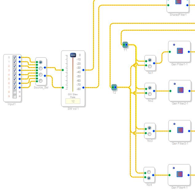
Notice that this is identical to the program shown in a previous section, except that we have added a new cell called Source_Sel. This selector takes up 4 locations in Parameter RAM, and with a little bit of toying with SigmaStudio we can determine how to program this cell. The first two inputs are the analog outputs of the A/D converter, and we can select that input by putting a “1” in the first address used by this cell, with zeros in the other three addresses. The next input is the first serial data input, which is called SDATA_IN0 in the data sheet and which comes into the chip on MP1 (pin10). We can select this input by setting the second address allocated to this cell as a “1” and make the others zero. So we have a rough idea how to program this selector, but we don’t have a clue what those Parameter RAM addresses are, because we haven’t compiled the project. So let’s compile the revised project and then export the system files.
After compiling the program, we run the “Create Cell Map” utility and we find that the Source_Sel has been assigned the address 0: AD1701control.Source_selector.Param_Addr = 0. So now we know where this cell is located in Parameter RAM and how to switch between the inputs. So we just need to write the code for the GUI and the appropriate handler code to generate the commands that go to the microprocessor. Here is how the GUI looks:
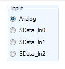
And here is the handler for the first button, which selects the analog input:
Private Sub Analog_in_CheckedChanged(sender As System.Object, e As System.EventArgs) Handles Analog_in.CheckedChanged
Main.BCD.Amp.Chip.Source = Source_select.Analog1
Call AD1701_Mux_update(1, Source_selector.Param_Addr)
Call AD1701_Mux_update(0, Source_selector.Param_Addr + 1)
Call AD1701_Mux_update(0, Source_selector.Param_Addr + 2)
Call AD1701_Mux_update(0, Source_selector.Param_Addr + 3)
End Sub
The AD1701_Mux_update routine just outputs the data to the specified address, so this routine sends a “1” to the first address and zeros to the next three, as we said was needed for the Source_Sel cell.
Warning: we must also update the code in the microprocessor
This example pointed out how the SigmaStudio compiler re-assigned the Parameter RAM addresses. Before our change, address 0 and 1 in the Parameter RAM controlled the left and right volume. And with our change, address 0 is used for the Source_Sel mux and the volume control cells got reassigned to addresses 4 and 5. So when the program executes in the ADAU1701, it will look for the volume control data in a different location in the Parameter RAM. So whenever we make a change to the SigmaStudio project, we must reassemble the code for the microprocessor so that the ADAU1701 code “matches” the Parameter RAM addresses that we are using in the ASD program. So we need to use the “Create Assembler Data” tool and reprogram the microprocessor whenever we make a change to the SigmaStudio program! This involves creating the assembler data and then pasting it into the appropriate assembler header file. And, of course, we need to recompile the microprocessor code and reprogram the Flash memory.
This requirement to keep the microprocessor and ASD program synchronized means that we need to be very careful to “finalize” the SigmaStudio project, because once the hardware with the microprocessor is deployed it may be difficult to make those changes.
Comparisons to the miniDSP Product
MiniDSP uses the ADAU1701 in the same way as described in this flow, but they obviously have their own tools for determining which Parameter RAM addresses are associated with specific cells. They load the ADAU1701 the same way as described here: from the microprocessor on their board (self-boot is not used). They use different USB hardware (not FTDI), and they have their own protocol for talking to the microprocessor on their board. But conceptually, the way the ADAU1701 is used is identical.
However, the ASD has several advanced features that make ADAU1701 development more interesting or flexible than miniDSP. First, ASD uses the Safeload Registers to update the Parameter RAM. This means that you can directly reprogram the ADAU1701 without having to stop the chip to resync it. This results in a faster, more responsive GUI. Second, the ASD code supports quick A/B testing by saving two images of the Parameter RAM in the microprocessor that can be switched back and forth. So you can rapidly toggle between two crossovers or two EQ settings for development testing. And third, ASD will eventually support user-generated SigmaStudio programs. Right now the SigmaStudio program must be programmed into the microprocessor using a microprocessor development tool, but in a future iteration the program will be able to download the ADAU1701 program and parameter RAM from the host computer.
Of course, the main differences between miniDSP and ASD are all of the capabilities provided by the host application, rather than how the ADAU1701 is programmed.